


3A2 3A1 2A2 2A1 1A2 1A1
3A2 3A1 2A2 2A1 1A2 1A1
INSTALLATION DIAGRAM:
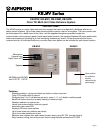
KB-MV2
Rear View
U
P
KB-SWM & KB-SWS
Rear View
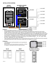
Installation:
- Mount the KB-SWM and KB-SWS into the GF-2F or GF-3F mounting bracket.
- Plug the KB-MV2 / KB-MV3 connector cable into the KB-SWM. If any KB-SWS sub-modules are used, plug the
KB-MV2 / KB-MV3 connector cable into the closest one, then plug its blue and yellow 10-pin connector into the next
switch module, daisy-chaining them together. Plug the last KB-SWS connector into the KB-SWM master switch module.
- Connect the black and white wire from the KB-MV2 / KB-MV3 connector cable to the SKK-620 power leads (cut spade
lug connectors). The white wire connects to +6VDC (black w/white stripe), and the black wire to -6VDC (solid black).
- Connect wires from KB-3MRD’s to corresponding terminals on the KB-SWM / KB-SWS. (1A1, 1A2 = upper button,
2A1, 2A2 = middle button, 3A1, 3A2 = lower button)
- Install completed entry panel into either the GF-2B / GF-3B (semi-flush mount) or GF-nHB (surface mount) as required.
- Use Aiphone series wire 871802. Wire must be 18AWG solid, non-shielded, PE insulation.
Initialization:
- The entrance panel must be powered on prior to powering the
tenant stations.
- After the entrance and tenant stations are powered on, initialize
the system by calling each tenant from each entry panel.
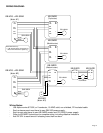
KB-SWM
KB-SWS
NOT USED
WHITE
BLACK
To + 6VDC
To - 6VDC
To KB-3MRD
To KB-3MRD
To KB-3MRD
To KB-3MRD
To KB-3MRD
To KB-3MRD
GF-2F
(frame & bracket)
GF-3F
(frame & bracket)
KB-SWM & KB-SWS’s
mounted in bracket
Page 2
Not Used
1A1, 1A2
2A1, 2A2
3A1, 3A2