


43-EN
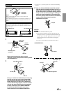
To prevent noise/interference in the audio system.
• Locate the unit and route the leads at least 10 cm away from the car harness.
• Keep the battery power leads as far away from other leads as possible.
• Connect the ground lead securely to a bare metal spot (remove any paint, dirt or grease if necessary) of the car chassis.
• If you add an optional noise suppressor, connect it as far away from the unit as possible. Your Alpine dealer carries various noise
suppressors, contact them for further information.
• Your Alpine dealer knows best about noise prevention measures so consult your dealer for further information.
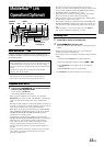
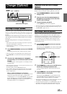
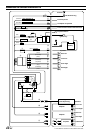
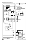
1 Antenna Receptacle
2 Audio Interrupt In Lead (Pink/Black)
Connect this lead to the Audio Interface output of a cellular
phone which provides ground shorting when a call is
received.
3 Remote Turn-On Lead (Blue/White)
Connect this lead to the remote turn-on lead of your
amplifier or signal processor.
4 Dimmer Lead (Orange) (CDA-9812RX only)
This lead may be connected to the vehicle’s instrument
cluster illumination lead. This will enable the vehicle’s
dimmer control to dim the backlighting of the unit.
5 Switched Power Lead (Ignition) (Red)
Connect this lead to an open terminal on the vehicle’s fuse
box or another unused power source which provides (+) 12V
only when the ignition is turned on or in the accessory
position.
6 Power Antenna Lead (Blue)
Connect this lead to the +B terminal of your power antenna,
if applicable.
• This lead should be used only for controlling the vehicle's power
antenna. Do not use this lead to turn on an amplifier or a signal
processor, etc.
7 Choke Coil with Fuse Holder (20A)
8 Battery Lead (Yellow)
Connect this lead to the positive (+) post of the vehicle's
battery.
9 ISO Power Supply Connector
! Ground Lead (Black)
Connect this lead to a good chassis ground on the vehicle.
Make sure the connection is made to bare metal and is
securely fastened using the sheet metal screw provided.
" Ai-NET Connector
Connect this to the output or input connector of other
product (CD changer, Equalizer, etc.) equipped with Ai-
NET.
# System Switch
When connecting a processor using Ai-NET, place this
switch in the EQ/DIV position. When no device is
connected, leave the switch in the NORM position.
• Be sure to turn the power off to the unit before changing the switch
position.
$ Power Supply Connector
% ISO Connector (Speaker Output)
& Left Rear (+) Speaker Output Lead (Green)
( Left Rear (–) Speaker Output Lead (Green/Black)
) Left Front (+) Speaker Output Lead (White)
~ Left Front (–) Speaker Output Lead (White/Black)
+ Right Front (–) Speaker Output Lead (Grey/Black)
, Right Front (+) Speaker Output Lead (Grey)
- Right Rear (–) Speaker Output Lead (Violet/Black)
. Right Rear (+) Speaker Output Lead (Violet)
/ Remote Control Interface Connector
To remote control interface box.
: Ai-NET Cable (Included with CD Changer)
; Front Output RCA Connectors
RED is right and WHITE is left.
< Rear Output RCA Connectors
RED is right and WHITE is left.
= Subwoofer Output RCA Connectors
RED is right and WHITE is left.
> RCA Extension Cable (Sold Separately)