


AVDINPC
5
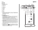
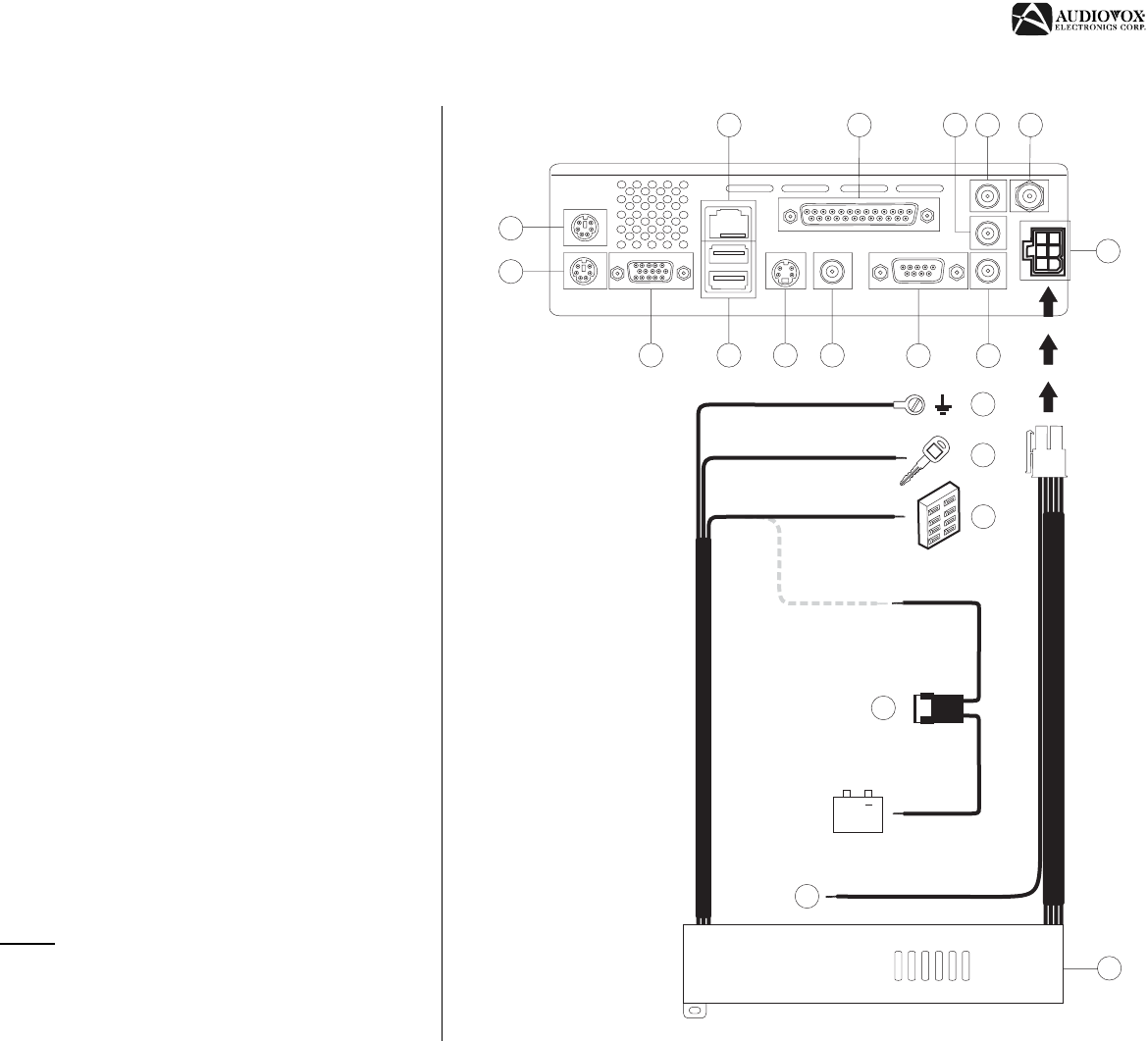
WIRING
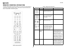
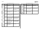
Wiring Connections
1. PS/2 Mouse
2. PS/2 Keyboard
3. VGA
4. LAN (RJ-45)
5. USB 1/USB 2
6. S-Video
7. RCA Video
8. Printer
9. COM Port
10. MIC In
11. Line Out
12. Line In
13. AC Adapter (Purchased Separately) – Only use an AC adapter with the
following specifications: Output – 12V, 4.3A; Input – 100-240V~1.5A, 50/
60Hz; Center pin (+) positive
14. Car Power Input
15. Power Supply
16. ILLUMINATION WIRE (yellow)
17. ACC POWER WIRE (red) – Connect to a +12 volt circuit that is only live
when the ignition is on. The best connection point is at the car’s fuse
block at the “RADIO” or “ACCESSORY” identified terminals.
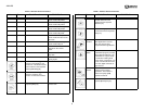
18. CONSTANT POWER WIRE (yellow) – Connect the 12V PLUS constant
power wire to a live 12 volt wire in the vehicle. Before making a
connection, check that the wire you intend to connect it to is always live,
even when the car’s ignition is turned off. If a live wire is not found, route
the wire to the car’s fuse block and connect it to a live circuit there.
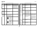
19. GROUND WIRE (black) – Securely fasten the Ground wire to a grounded
metal part of the car’s chassis. If you cannot find an existing bolt or screw
to fasten it to, drill a hole in the metal and secure it with a screw. To
ensure a good ground, remove any paint or grease from areas where the
wire will contact the surface.
20. INLINE FUSE (red) – When running the red ACC Power wire directly to
the battery, the inline fuse MUST
be connected between the unit and the
battery (within 18” of the battery). If the ACC Power wire is connected to
the fuse block, the inline fuse is not required.
1
3
4
5
6
2
7
8
9
10
11 12
13
14
15
16
17
18
19
Black
Yellow
Red
Yellow
+
Red
Red
20
BATTERY
FUSE BOX
Figure 3: Wiring Connections