


Printed in China / / 2005/12 (A•C) 284-0727-00
1. This set is exclusively for use in cars with a
negative ground, 12 V power supply.
2. Read these instructions carefully.
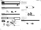
3. Be sure to disconnect the battery “-
” terminal
before starting. This is to prevent short circuits
during installation. (Figure 1)
-
Notes:
1) Some car models require special mounting kits for proper
installation. Consult your Clarion dealer for details.
2) Fasten the front stopper securely to prevent the source unit
from coming loose.
1. When removing the source unit, disassemble it in the reverse of the
order in Section “3. INSTALLING THE SOURCE UNIT”.
2. Press the outer escutcheon upward and remove it. (Figure 8)
3. Insert and lock the hook plates. (Figure 9)
4. Pull the hook plates to remove the source unit.
Installation/Wire Connection Guide
1. Prepare all articles necessary for installing the source unit before
starting.
2. Install the unit within 30° of the horizontal plane. (Figure 2)
3. If you have to do any work on the car body, such as drilling holes,
consult your car dealer beforehand.
4. Use the enclosed screws for installation. Using other screws can
cause damage. (Figure 3)
2.
CAUTIONS ON INSTALLATION / /
3.
INSTALLING THE SOURCE UNIT / /
■ Universal Mount
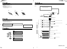
1. Place the universal mounting bracket into the instrument panel, use
a screwdriver to bend each stopper of the universal mounting
bracket inward, then secure the stopper as shown in Figure 4.
2. Wire as shown in Section 8.
3. Insert the source unit into the universal mounting bracket until it
locks.
4. Mount the outer escutcheon so that all the hooks are locked.
■■
4.
REMOVAL OF THE SOURCE UNIT / /
1.
BEFORE STARTING / /
-
English
English
English
English
Car battery
Max. 8 mm / 8 mm / 8 mm
Chassis / /
Chassis / /
Damage / /
Max. 30˚ / 30˚ / 30˚
Figure 2 / 2 / 2 Figure 3 / 3 / 3
Figure 1 / 1 / 1
(182 mm)
Outer escutcheon
Instrument panel
Hole
Hexagonal bolt
Stoppers
Stoppers
Screwdriver
Universal mounting bracket
Strap
*
This part is not provided in some models.
*
*
Source Unit
• Console opening dimensions
•
•
Hole
53 mm
Note:
Before attaching the universal mounting bracket, slightly bend
the spring toward the inside with your fingers and attach it to the
side of car.
Top
Bottom
Installation direction
Outer escutcheon side view
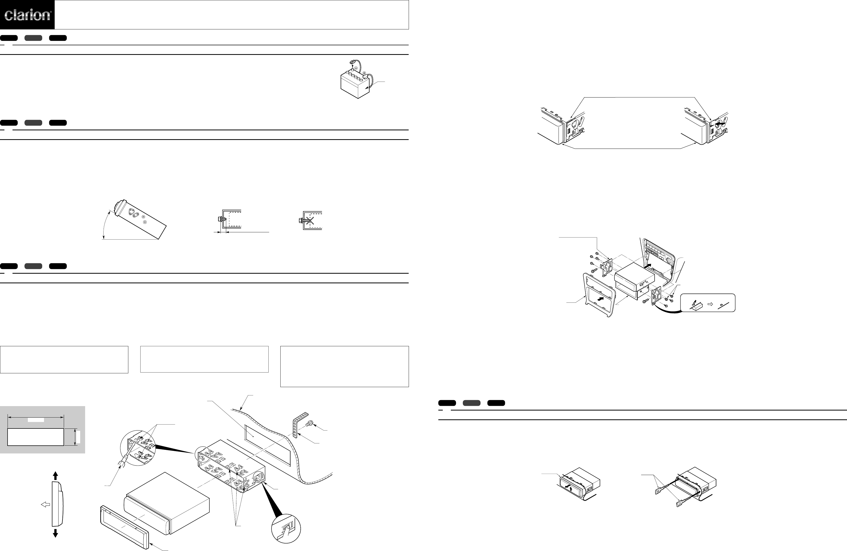
■ Fixed Mount
(TOYOTA, NISSAN and other ISO/DIN equipped vehicles)
This unit is designed for fixed installation in the dashboard.
If the vehicle is equipped with a factory-installed radio, install the
source unit with the parts and screws marked (★) (Figure 7).
If the vehicle is not equipped with a factory-installed radio, obtain an
installation kit to install the source unit in the following procedure.
Bend the stopper following the procedures below when this source
unit is installed to the TOYOTA, NISSAN and other ISO/DIN equipped
vehicles.
1. Bend the stopper from the source unit. (Figure 5, 6)
■
★
■
★
2. Secure the mounting brackets to the chassis as shown in Figure 7.
Holes are pre-tapped for TOYOTA and NISSAN vehicles; modifica-
tion, such as drilling new holes, of the mounting brackets may be
required for other models.
3. Wire as shown in Section 8.
4. Secure the unit in the dashboard, and then reassemble the
dashboard and the center panel.
Center Panel (Note 1)
1
1
Figure 7 / 7 / 7
Source Unit
Mounting bracket
*
(1 pair for the left and right sides)
*
*
Dashboard
Pocket
★
★
★
★
★
4–Hexagonal screw
*
(M5
×
8)
4
*
(M5
×
8)
4
*
M5
×
8
Note 2 / 2 / 2
★
STOPPER / /
SOURCE UNIT / /
BEFORE BEND / /
AFTER BEND / /
Figure 5
/
5
/
5 Figure 6
/
6
/
6
∗ : The parts and screws with this mark are used to install radio or
included in the installation kit.
★ : The screws with this mark are originally attached to the vehicle.
Note 1:In some cases, the center panel may require some modifica-
tion (trimming, filling, etc.).
Note 2:If a hook on the installation bracket interferes with the unit,
bend and flatten it with a nipper or a similar tool.
Figure 8 / 8 / 8
2–Hook plate
2
2
Outer escutcheon
Figure 9 / 9 / 9
∗
★
∗
★
Figure 4 / 4 / 4
05.11.23, 15:461