


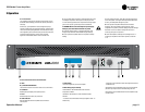

CDi Series Power Amplifiers
Operation Manual
page 11
3.1 Precautions
Your amplifier is protected from internal and external faults, but you
should still take the following precau tions for optimum performance
and safety:
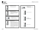
1. Before use, your amplifier first must be config ured for proper
operation, including input and output wiring hookup. Improper wiring
can result in serious operating difficulties. For information on wiring
and configuration, please consult the Setup section of this manual or,
for advanced setup techniques, con sult Crown’s Amplifier
Application Guide available online at www.crownaudio.com.
2. Use care when making connections, selecting signal sources and
controlling the output level. The load you save may be your own!
3. Do not short the ground lead of an output cable to the input signal
ground. This may form a ground loop and cause oscillations.
4. WARNING: Never connect the output to a power supply,
battery or power main. Elec trical shock may result.
5. Tampering with the circuitry, or making unautho rized circuit
changes may be hazardous and invali dates all agency listings.
6. Do not operate the amplifier with the red Clip LEDs constantly
flashing.
7. Do not overdrive the mixer, which will cause clipped signal to be
sent to the amplifier. Such sig nals will be reproduced with extreme
accuracy, and loudspeaker damage may result.
8. Do not operate the amplifier with less than the rated load
impedance. Due to the amplifier’s output protection, such a
configuration may result in pre mature clipping and speaker damage.
Remember: Crown is not liable for damage that results from
overdriving other system components.
9. Crown CDi amplifiers can directly drive 70V/high-Z loads. To
configure your amplifier for this mode of operation, see Section
4.1.6.
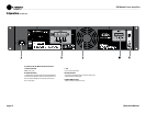
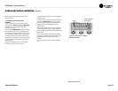
3 Operation
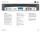
2000
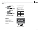
A. Grille
B, D, E. Sel/Prev/Next Buttons
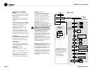
Three buttons near the LCD screen are used to access menu items.
C. LCD Screen
Backlit liquid crystal display shows speaker presets.
F. Level
Detented rotary level control, one per channel.
H. Power Indicator
Blue LED illuminates when the amplifier has been turned on
and has power.
I. Power Switch
On/off switch applies AC power to the amplifier.
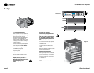
G. Meter Group (one per channel)
Thermal Indicator: Red LED illuminates under excessive
temperature conditions.
Clip Indicator: Red LED turns on at the threshold of audible
distortion.
–10 Indicator: Green LED flashes when output signal exceeds –10
dB below clip.
–20 Indicator: Green LED flashes when output signal level exceeds
–20 dB below clip.
Signal Indicator: Green LED flashes when a very low-level signal is
present at input. May be used for troubleshooting cable runs.
Ready Indicator: Green LED illuminates when the amplifier is ready
to produce audio.
3.2 Front Panel Controls and Indicator