


R4140G FLAME SAFEGUARD PROGRAMMING CONTROLS
60-2337—3
3
NOTE: Allowable inrush can be up to ten times the pilot duty
rating.
EXAMPLE: Pilot duty rating = 50 VA.
At 120V, running current is:
50
120
= 0.42A
.
Maximum allowable inrush is ten times
0.42A = 4.2A.
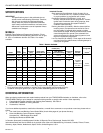
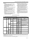
Interlock Ratings:
See Table 3.
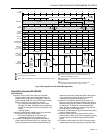
Table 3. Interlock Ratings.
Ambient Operating Temperature Ratings:
Minimum: Minus 40°F (minus 40°C).
Maximum:
Interlocks
Requirements must be abIe to
carry and break current to:
Limits, Burner Controller,
and Running Interlocks
(including airflow switch)
Ignition transformer, pilot valve,
and main fuel valve(s).
Start or Preignition
Interlocks
Programmer relay 1K (5W max).
Storage Temperature Ratings:
Minus 60°F to plus 150°F (minus 51°C to plus 66°C).
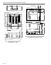
Mounting:
3-sided Q520A1089 Wiring Subbase, or 4-sided Q520A1121
Wiring Subbase; both have 20 knife-blade contacts (subbase
ordered separately).
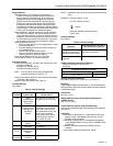
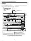
Dimensions:
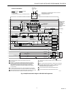
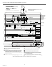
See Fig. 1 and 2.
Weight (Without Plug-in Flame Signal Amplifier and
202050C Cover):
4 lb, 12 oz (2.15 kg).
Flame Detection System (Ordered Separately):
Plug-in Flame Signal Amplifier and matching Flame Detector;
see Table 4.
Approvals:
Underwriters Laboratories Inc. Listed Section of Primary
Safety Control (120V Models With Covers): File No.
MP268; Guide No. MCCZ.
Underwriters Laboratories Inc. Component Recognized
(120V Models Without Covers): File No. MP268; Guide
No. MCCZ2.
Canadian Standards Association Certified: File No.
LR1620.
Factory Mutual Approved: Report No. 24180.
Programmer Mounting Position
Standard Vertical (With Handle Up) Any Other
+150°F (+66°C) +135°F (+57°C)
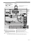
Safety Features:
Safe Start Check—For the presence of a flame (or a
condition simulating a flame) provided at startup and
during prepurge. If the flame relay 2K is pulled in at
startup, 2K2 is open and the programmer cannot be
started. If the flame relay 2K pulls in during prepurge
(before 57.5 seconds), 2K2 opens, relay 1K drops out,
and ignition trials cannot be started. Instead, the timer
completes its revolution and stops at the standby position
(zero seconds). If the flame relay 2K drops out by the end
of the cycle, the programmer restarts the system.
Safety Shutdown—Ignition transformer and all automatic
fuel valves de-energize. The lockout switch trips and
locks out the programmer. If used, the external alarm is
energized. The timer completes its revolution and locks
up at the stand-by position (zero seconds). The lockout
switch must be manually reset to restart the system.
Safety Shutdown occurs on:
• Failure to ignite the pilot (or first stage burner if using
direct spark ignition).
• Failure to light the main burner (unless monitoring
an intermittent pilot).
• Loss of flame during the Run period.
• Failure in the flame detection system (if a self-
checking system is used, see Table 4).
Flame Failure Response Time—2 to 4 seconds.
Lockout Switch Timing—30 seconds (nominal).
Electrical Ratings:
Voltage and Frequency: 120 Vac (102V minimum to 132V
maximum), 50/60 Hz.
R4140G1114: 240 Vac, 60 Hz.
R4140G1122: 208 Vac, 60 Hz.
NOTE: Use of a 50 Hz power supply lengthens the
sequence timings by a factor of 1.2.
Power Consumption (With No Loads Connected to Output
Terminals): 13W maximum.
Maximum Total Connected Load: 2000 VA.
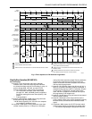
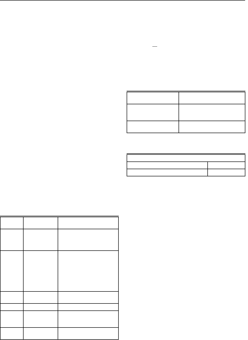
Terminal Ratings:
See Table 2.
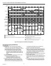
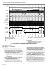
Table 2. Terminal Ratings.
Terminal Typical Load
Maximum Rating at
120 Vac, 60 Hz
5 or 6 Ignition
Transformer/Pilot
Valve/First Stage
Fuel Valve
4.5A ignition and 50 VA pilot duty or
2.5A ignition and 75 VA pilot duty
7 Main Fuel Valve(s)
(solenoid/motorized
/diaphragm) and
Vent Valve if
required
250 VA pilot duty or 65 VA pilot duty
in parallel with motorized valve(s)
using a total of 1150 VA locked
rotor (inrush),460 VA to open, and
250 VA to hold or motorized
valve(s) using a total of 1500 VA
locked rotor (inrush), 600 VA to
open, and 250 VA to hold
8 Burner Motor
(blower)
9.8A full load, 58.8A locked rotor
(inrush)
9 120V Alarm 75 VA pilot duty
10, 11, 12,
and 14
Firing Rate
(damper) Motor
Contacts
50 VA pilot duty
18
(if available)
Ignition
Transformer
4.5A ignition