


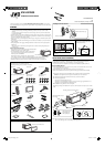
When installing the unit in a Nissan car
Plate for use with a Nissan car
KW-AVX900
Installation/Connection Manual
0307MNMMDWJEIN
EN
©2007 Victor Company of Japan, Limited
LVT1670-005A
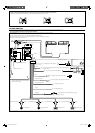
[A]
This unit is designed to operate on 12 V DC, NEGATIVE ground electrical systems. If your vehicle
does not have this system, a voltage inverter is required, which can be purchased at JVC car audio dealers.
WARNINGS
• DO NOT install any unit and wire any cable in locations where;
– it may obstruct the steering wheel and gearshift lever operations, as this may result in a traffic
accident.
– it may obstruct the operation of safety devices such as air bags, as this may result in a fatal accident.
– it may obstruct visibility.
• DO NOT operate any unit while manipulating the steering wheel, as this may result in a traffic accident.
• The driver must not watch the monitor while driving. If the driver watches the monitor while driving, it
may lead to carelessness and cause an accident.
• The driver must not put on the headphones while driving. It is dangerous to shut off the outside sounds
while driving.
• If you need to operate the unit while driving, be sure to look around carefully or you may be involved in
a traffic accident.
• If the parking brake is not engaged, “Parking Brake” flashes on the monitor, and no playback picture
will be shown.
– This warning appears only when the parking brake wire is connected to the parking brake system
built in the car.
Notes on electrical connections:
• Replace the fuse with one of the specified rating. If the fuse blows
frequently, consult your JVC car audio dealer.
• It is recommended to connect to the speakers with maximum
power of more than 50 W (both at the rear and at the front,
with an impedance of 4 Ω to 8 Ω).
If the maximum power is less than 50 W, change “Amplifier
Gain” setting to prevent the speakers from being damaged (see page 60 of the INSTRUCTIONS).
• To prevent short-circuit, cover the terminals of the UNUSED leads with insulating tape.
• The heat sink becomes very hot after use. Be careful not to touch it when removing this unit.
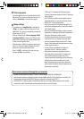
Heat sink
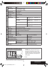
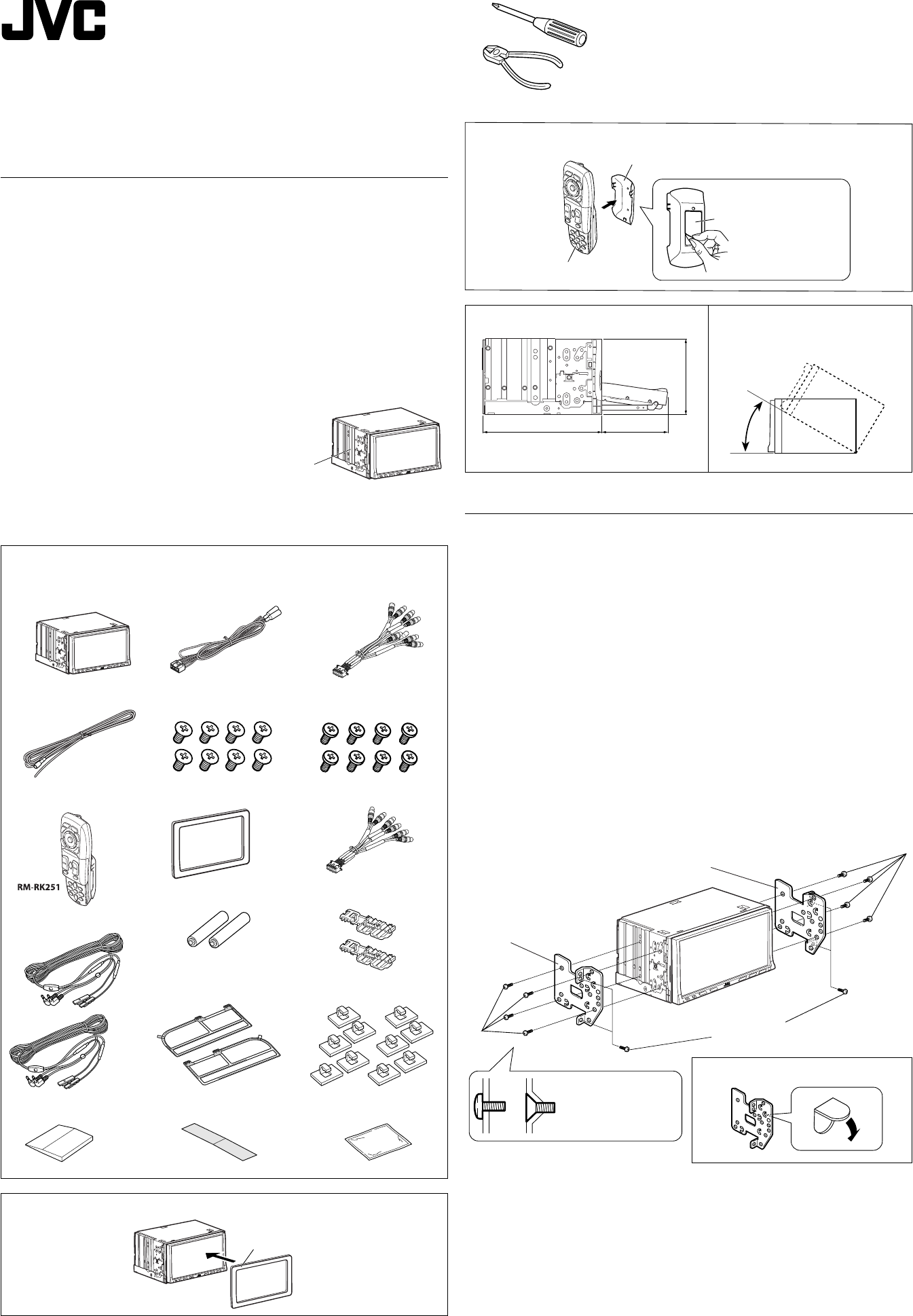
Installing the remote controller
Install the unit at an angle of less than 30˚,
taking it into account that the monitor
would eject when in use.
30˚
160
90.4
100
Required space for the monitor ejection
Unit: mm
Holder
Double-sided adhesive tape
Remote controller
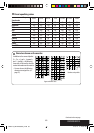
Parts list for installation and connection
The following parts are provided for this unit.
If anything is missing, contact your dealer immediately.
Main unit
Power cord
AV I/O cord
Round head screws
(M5 x 8 mm)
Flat head screws
(M5 x 8 mm)
Reverse gear signal extension cord
Remote controller / Holder
Batteries
5.1CH (LINE OUT) cord
Crimp connectors
Plate for use with a Nissan car
1
TV aerials
Rubber spatula Cleaner
Clamps
Earth tape
Aerial cords
Note : When installing the unit on the mounting bracket, make sure to use the supplied screws
(M5 x 8 mm). If longer screws are used, they could damage the unit.
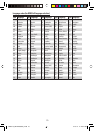
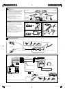
INSTALLATION (IN-DASH MOUNTING)
The following illustration shows a typical installation. However, you should make adjustments
corresponding to your specific car. If you have any questions or require information regarding
installation kits, consult your JVC car audio dealer or a company supplying kits.
• If you are not sure how to install this unit correctly, have it installed by a qualified technician.
Before installing the unit
• When mounting the unit, be sure to use the screws provided, as instructed. If other screws are used,
parts could become loose or damaged.
• When tightening screws or bolts, be careful not to pinch any connection cord.
• Make sure not to block the fan on the rear panel to maintain proper ventilation when installed.
1 Remove the audio system originally installed in the car, together with its mounting brackets.
Note: Be sure to keep all the screws and parts removed from your car for future use.
2 Attach the mounting brackets (removed from the car), to this unit (see below).
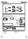
3 Connect the supplied cords.
• See page 2 for connecting the power cord.
• See page 3 for connecting the TV aerials, AV I/O cord and reverse gear signal extension cord.
• See page 4 for connecting the 5.1CH (LINE OUT) cord.
4 Install this unit using the screws removed in step 1.
The following example is for installation in a Toyota car. For more details, consult your JVC car audio
dealer.
Screws removed from the car in step
1
Supplied screws
Mounting bracket removed
from the car
Mounting bracket removed from the car
Supplied
screws
Select the appropriate
type fitting to your
audio system space.
If necessary, restore the protruding tabs.
Instal_KW-AVX900[A]_1.indd 1Instal_KW-AVX900[A]_1.indd 1 2007.3.20 1:12:26 PM2007.3.20 1:12:26 PM