


JIIIII~~IIIII~~~~~~I~~IIIII~~IIIII~~IIII~~~IIIII~~IIIII~~IIIII~~IIIII~~IIIII~~IIIII~~IIII~~~IIIII*~IIIII~IIIIII~~IIIII-~IIII~~~IIIII~~IIIII~~IIII~~~IIIII~~I~III~~IIIII*~IIIII~~IIIII~~IIIII*~IIII~~~IIII~~~IIII~
-
-
-
- -
!
-
-
SECTION
2.
CONTROLS AND THEIR FUNCTIONS
I
-
-
~~~~~~~~~~~~~~~~~~~I~-~IIII~.~IIII~~~IIII~.~~III~.~IIII~~~IIII~.~IIII~.~IIII~.~IIII~.~II~I~.~IIII~.~IIII~.~IIII~.~IIII~.~IIII~.~IIII~.~IIIII.~IIII~.~IIII~.~IIII~.~IIII~.~IIII~.~IIII~.~IIII~.~IIII~.~IIII~.~IIII~~
PULL
LAMP
ANTENNA TUNER AT-
130
r
71
r
71
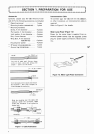
Figure
2-1
I
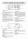
Front view
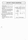
1.
Meter
The meter reads SWR (standing-wave ratio) and
may be illuminated by an external power source.
2.
CAL (Calibrate)/SWR Switch
To measure SWR, first
set
this switch to the
CAL
(1)
position. Adjust the CAL control until
the meter pointer swings to the CAL line on
the meter scale.
Then depress the switch to the SWR
(1)
position,
and read the SWR.
3.
CAL (Calibrate) ControlIMeter Lamp Switch
Before measuring SWR, this control
is
used to
calibrate the meter. Adjust
as
described above
in item
2.
The meter lamp lights when the
control
is
pulled ON.
4.
BAND Switch
Set this switch to the band in which you are
operating. The BAND switch also has
a
"THROUGH" position at which the antenna
is
connected directly to the transceiver. SWR can
also be measured
at
the THROUGH position.
CAUTION: DO NOT operate the band switch
while transmitting. Equipment
damage
WI LL occur.
5.
R TUNE
The
R
TUNE adjusts the resistive component of
antenna impedance.
b
6.
X
TUNE (~ransmit ~unin~) Control
The
X
TUNE adjusts the reactive component of
antenna impedance.
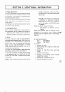
Figure
2-2.
Rear View
1.
Serial No. Plate
4.
INPUT Connector
This plate
is
stamped with the Serial Number of
The INPUT UHF connector accepts the H
F
input
your unit.
signal fed from the antenna connector on the
2.
GND post
transceiver.
Connect the GND
post to the transceiver GND
5.
ANT
Connector
stud. Use
as
short
a
cable
as
possible, using the
The ANT UHF
connector
accepts
the
antenna
supplied ground lug.
coaxial cable.
3.
12V
DC
Accepts 12V DC for meter illumination. Use the
supplied plug.
NOTE: Viewed from the rear, the right terminal
is POSITIVE.