


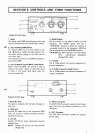
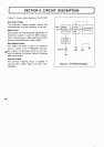
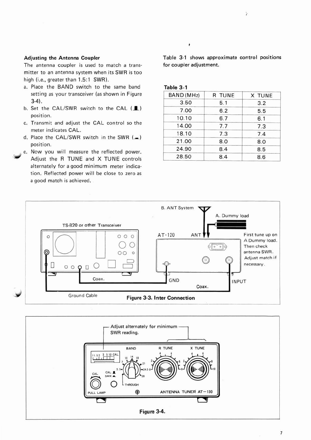
Adjusting the Antenna Coupler
The antenna coupler
is
used to match a trans-
mitter to an antenna system when
its
SWR
is
too
high
(i.e.,
greater than
1.5:1
SWR).
a.
Place the BAND switch to the same band
setting as your transceiver
(as
shown in Figure
3-41,
b. Set the CALISWR switch to the CAL
(I)
position.
c. Transmit and adjust the CAL control so the
meter indicates CAL.
d. Place the CALISWR switch in the SWR
(,)
position.
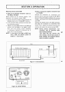
e.
Ncw you will measure the reflected power.
Adjust the
R TUNE and
X
TUNE controls
alternately for
a
good minimum meter indica-
tion. Reflected power will be close to zero
as
a
good match
is
achieved.
Table
3-1
shows approximate control positions
for coupler adjustment.
Table
3-1
I
BAND(MHz1
I
R
TUNE
I
X
TUNE
I
--
-p
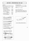
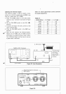
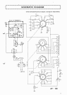
B.
ANT
System
A.
Dummy load
TS-820
or other Transceiver
f--
1
I
I
.-
.-a
~.
-
1
-
-
000
AT-
120
ANT
First tune up on
-
-
I
i
oo!l
I
A
Dummy load.
4
1
Then check
I19
M
-
I I
oooll
I!
-
-
ll
_
..
.
.-
antenna SWR.
necessary.
r71
-
--
.~
Coax.
INPUT
Coax.
Ground Cable
Figure
3-3.
Inter Connection
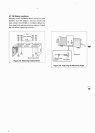
-Adjust
alternately for minimum
4
SWR
reading.
BAND
R
TUNE
X
TUNE
PULL
LAMP
@
ANTENNA
TUNER
AT-
130
c
.',
Figure
3-4.