


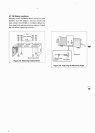
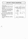
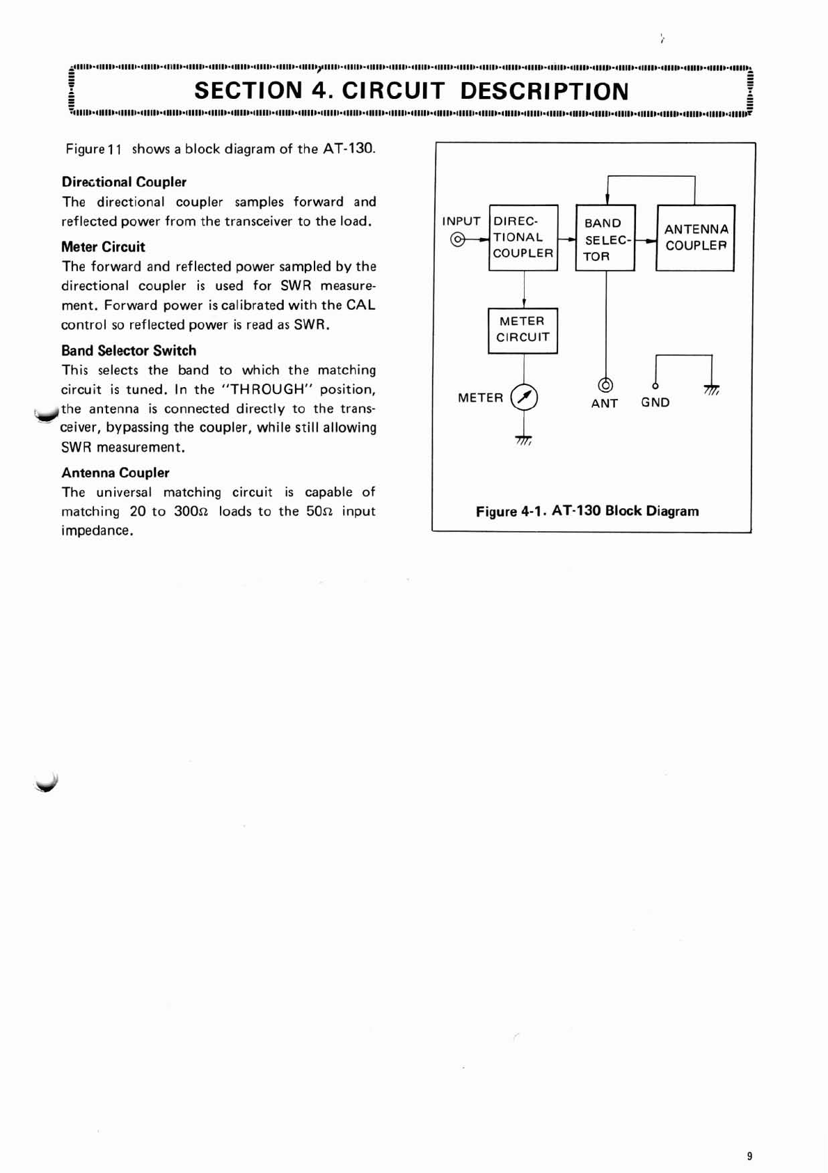
Figure 11 shows
a
block diagram of the AT-1
30.
Direcltional Coupler
The directional coupler samples forward and
reflected power from the transceiver to the load.
Meter Circuit
The forward and reflected power sampled by the
directional coupler
is
used for SWR measure-
ment. Forward power
is
calibrated with the
CAL
control so reflected power
is
read
as
SWR.
Band Selector Switch
This selects the band to which the matching
circuit
is
tuned. In the "THROUGH" position,
Idthe antenna
is
connected directly to the trans-
-
ceiver, bypassing the coupler, while
still
allowing
SWR measurement.
Antenna Coupler
The universal matching circuit
is
capable of
matching
20
to
300n
loads to the
50a
input
impedance.
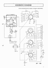
1
ANTENNA
COUPLER
INPUT
I
METER
CIRCUIT
@
n
ANT GND
Figure
4-1.
AT-130 Block Diagram
i
DIREC-
TIONAL
COUPLER
-c
BAND
SELEC---c
TOR