


CIRCUIT DESCRIPTION
4.
Transmitter System
4-1.
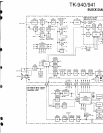
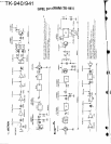
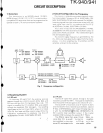
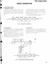
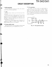
Microphone amplifier
The signal from the microphone goes to the
The signal is applied to the IC212 summing amplifier
nxcrophone mute switch (Q201 off). It then passes and mixed with QT and DQT from the CPU (IC209). It
through the high-pass filter in
IC205 (212) and the pre-
then passes through
the splatter filter (the fourth low-
emphasis/lDC circuit
in
IC205 (112). (If the option has
pass filter) consisting of
IC21 1 (112, 2/2), which
been installed, the signal
is mixed with the encode removes unwanted harmonics.
signal.)
The output from the low-pass filter is input to the Dl
A
converter (lC6) to adjust the modulation.
Fig. 3 Microphone amplification
0201 IC205 (212) IC205 (112) IC212 IC211 (212) IC211 (112)
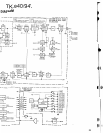
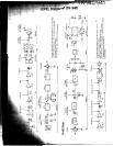
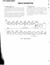
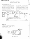
4-2. Final amplifier
4-3. APC circuit
The signal from the
PLL
is amplified
by
two power
The direct current that flows through the final
modules
(ICI 2 and IC14) to an output level of 15W, and
module
(lC14) produces a voltage across resistors
goes through the harmonic filter and antenna switch
R108, R109, and R110. This voltage is applied to pin
6
D20, and on to the antenna terminal.
of
lC13 (2/2), and is input as the reference voltage
IC13 (1/2) compares the DC input to pin 2 with the
difference of pin
5
and amplified.
reference voltage at pin 3 applied
by
IC8 (1121,
amplifies the result, and controls the DC amplifier (Q22
and Q23) to keep the transmit final current constant,
thus keeping the transmit output constant.
DRIVER
DRIVER
DATA
HPF
From
~icro~hone-
-
+
IDC
+
SUM
--B-
LPF
DRIVE
MIC
MUTE
Fig. 4 Transmit power circuit and APC circuit
LpF
POWER
AMP
I
I
025 026
MO"DIAConverte'
IC6
D20
ANT SW
I
DC
AMP DET
SW
-
-
8T
-I)).
I
SW
I
-
DC
-
A
A
ElC209
LPF