


52
12 OPERATOR CONVENIENCES
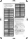
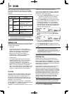
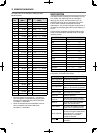
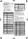
Antenna Selection Frequency Range (MHz)
0.03 ~ 0.522 10.5 ~ 14.5
0.522 ~ 2.5 14.5 ~ 18.5
2.5 ~ 4.1 18.5 ~ 21.5
4.1 ~ 6.9 21.5 ~ 25.5
6.9 ~ 7.5 25.5 ~ 30.0
7.5 ~ 10.5 30.0 ~ 60.0
Note: Connect an external tuner to the ANT 1 connector
only, then select ANT 1. The internal antenna tuner will be
automatically bypassed when the transceiver is switched ON.
APO (Auto Power OFF)
You can set the transceiver to switch OFF
automatically if no keys or controls are pressed or
adjusted for a certain period of time. One minute
before the transceiver switches OFF, “CHECK” is
output in Morse code.
1 Press [MENU], then press [Q-M.IN]/ [Q-MR] or
turn the MULTI/CH control to access Menu No. 86.
2 Press [M.IN]/ [SCAN (SG.SEL)] to select the APO
time from “oFF”, “60”, “120”, or “180” minutes.
3 Press [MENU] to exit Menu mode.
Note:
◆ The APO function works even if the transceiver is scanning.
◆ The APO timer starts counting down when no key presses,
no control adjustments, and no command (COM connector)
sequences are detected.
AUTOMATIC ANTENNA TUNER
As explained in “ANTENNA CONNECTION”
{page 1}, matching the impedance of the coaxial cable
and antenna is important. To adjust the impedance
between the antenna and the transceiver, you have
the choice of using the internal antenna tuner or an
external antenna tuner. This section describes how
to use the internal antenna tuner. For the external
antenna tuner, consult the instruction manual that
comes with the tuner.
1 Select the transmit frequency.
2 Press and hold [PRE (ANT 1/2)] to select “ ”
or “ ”.
• If the external antenna tuner (AT-300) is
connected to the ANT 1 connector, select
ANT 2 to use the internal antenna tuner.
The internal antenna tuner is automatically
bypassed if the external antenna tuner is
connected to ANT 1.
3 Press and hold [AT (TUNE)].
• CW mode is automatically selected and tuning
begins.
• “ ” blinks and the TX-RX LED lights red.
• To cancel tuning, press [AT (TUNE)] again.
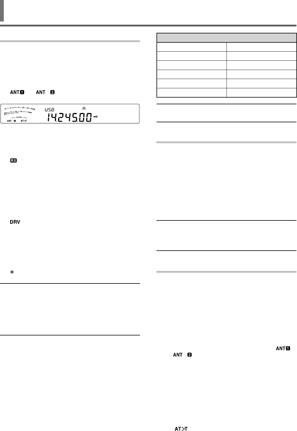
ANTENNAS
ANT 1/ ANT 2
Two antenna connectors are available for the HF/
50 MHz band on the TX/ RX unit rear panel.
Press and hold [PRE (ANT 1/2)] to select ANT 1 or
ANT 2.
• “ ” or “ ” appears to indicate which
antenna is selected.
RX ANT
Press and hold [ATT (RX ANT)] to toggle the RX ANT
between enabled and disabled.
• “
” appears when the RX ANT is enabled.
DRV
Press and hold [METER (DRV)] to switch the Drive
output (DRO) or Antenna output (ANT) between
enabled and disabled.
Drive output : Use the standard input of 1 mW for the
linear amplifi er and other connections.
• “ ” appears when the Drive output is enabled.
Antenna output: The DRV terminal functions as an
antenna output terminal for an external receiver. With
this function, the RX signal that is input from the
currently selected antenna (ANT1, ANT2, or RX ANT)
is split in the middle, with one input to the RX circuit
and the other output to the DRV terminal.
• “
” appears when the DRV (Antenna output) is
enabled.
Note:
◆ When you use the Antenna output function, due to the loss
of the splitter, the receive sensitivity and gain decreases by
approximately 3 dB.
◆ During transmission, the transmission output will leak a
little through internal isolation (approximately -20 dBm at 50
MHz).
◆ The ON/OFF status of the Antenna output function is stored
separately in the 50 MHz band and HF band.
■ Selecting the DRV Connector Function
1 Press [MENU], then press [Q-M.IN]/ [Q-MR] or
turn the MULTI/CH control to access Menu No.
85.
2 Press [M.IN]/ [SCAN (SG.SEL)] to select
“DRO” or “ANT”.
3 Press [MENU] to exit Menu mode.
The ANT 1, ANT 2, RX ANT, and DRV settings will
automatically be stored in the antenna band memory.
The next time you select the same band, the same
antenna will be automatically selected.