


72
13 CONNECTING PERIPHERAL EQUIPMENT
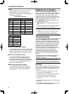
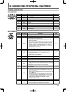
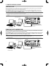
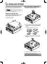
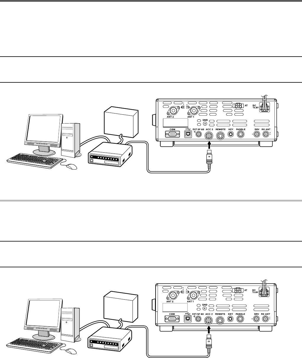
CONNECTING TO A TNC
When the transceiver is set to DATA mode and you are operating packet communications using an external TNC
(Terminal Node Controller), perform the connections as below.
Use the ACC2 connector to connect with an external TNC. Connect the external TNC modulation output line to
pin 11 (ANI) of the ACC2 connector, demodulation input line to pin 3 (ANO) of the ACC2 connector, and transmit
control (PTT) line to pin 13 (PKS) of the ACC2 connector.
Note:
◆ Do not share a single power source between the TNC and the transceiver.
◆ Keep as much space as possible between the transceiver and computer, and between the TNC, to prevent the transceiver from picking
up noise.
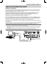
TS-590SG
TNC
Power supply for TNC
Personal computer
Supplied 13-pin DIN Plug (Use a
self-made connection cable using
the 13-pin DIN plug supplied with the
transceiver.)
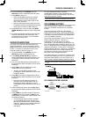
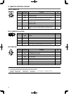
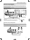
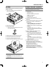
CONNECTING TO RTTY EQUIPMENT (FSK)
When the transceiver is set to FSK mode and you are operating RTTY (FSK) using an MCP (Multi Communication
Processor) or RTTY equipment, perform the connections as below.
Use the ACC2 connector to connect to the RTTY equipment. Connect the RTTY equipment keying output line to pin
2 (RTTY) of the ACC2 connector and demodulation input line to pin 3 (ANO) of the ACC2 connector. Additionally,
connect the transmit control (PTT) line to pin 13 (SS) of the ACC2 connector.
Note:
◆ Do not share a single power source between the MCP/RTTY unit equipment and the transceiver.
◆ Keep as much space as possible between the transceiver and computer, and between the RTTY equipment, to prevent the transceiver
from picking up noise.
TS-590SG
Power supply for RTTY unit
Personal computer
Supplied 13-pin DIN Plug (Use a
self-made connection cable using
the 13-pin DIN plug supplied with the
transceiver.)
RTTY unit