


Pacic Accessory Corporation - Santa Ana, CA 92705
techsupport@pac-audio.com • Voice: 866-931-8021 • Fax: 714-835-3233 • www.pac-audio.com
DISCLAIMER: Under no circumstances shall the manufacturer or the distributors of the C2R-VW2 be held liable for consequential damages sustained in
connection with the C2R-VW2. The manufacture and it’s distributors will not, nor will they authorize any representative or any other individual to assume
obligation or liability in relation to the C2R-VW2 other than its replacement.
01-04-10
J1850
Class 2
VPW
Class 2
J1850
100011101111001001101100
111010000110110111001100
Arbitration
EOD
CRC
100011101111001001101100
111010000110110111001100
Class 2
Class 2
J1850
Radio Replacement Interface
with Nav Outputs for select
Volkswagen CANbus Vehicles With
or Without Premium Audio Systems
C2R-VW2
Installation Notes:
For the most current and up-to-date application guide please visit www.pac-
audio.com
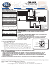
1. Vehicles with or without a factory amplier: Connect the aftermarket radio’s
front and rear speaker wires to the 16 pin plug.
2. The accessory output wire is located on the 11 pin CAN INTERFACE harness
- connect this wire to the radio’s accessory wire. The accessory wire supplies
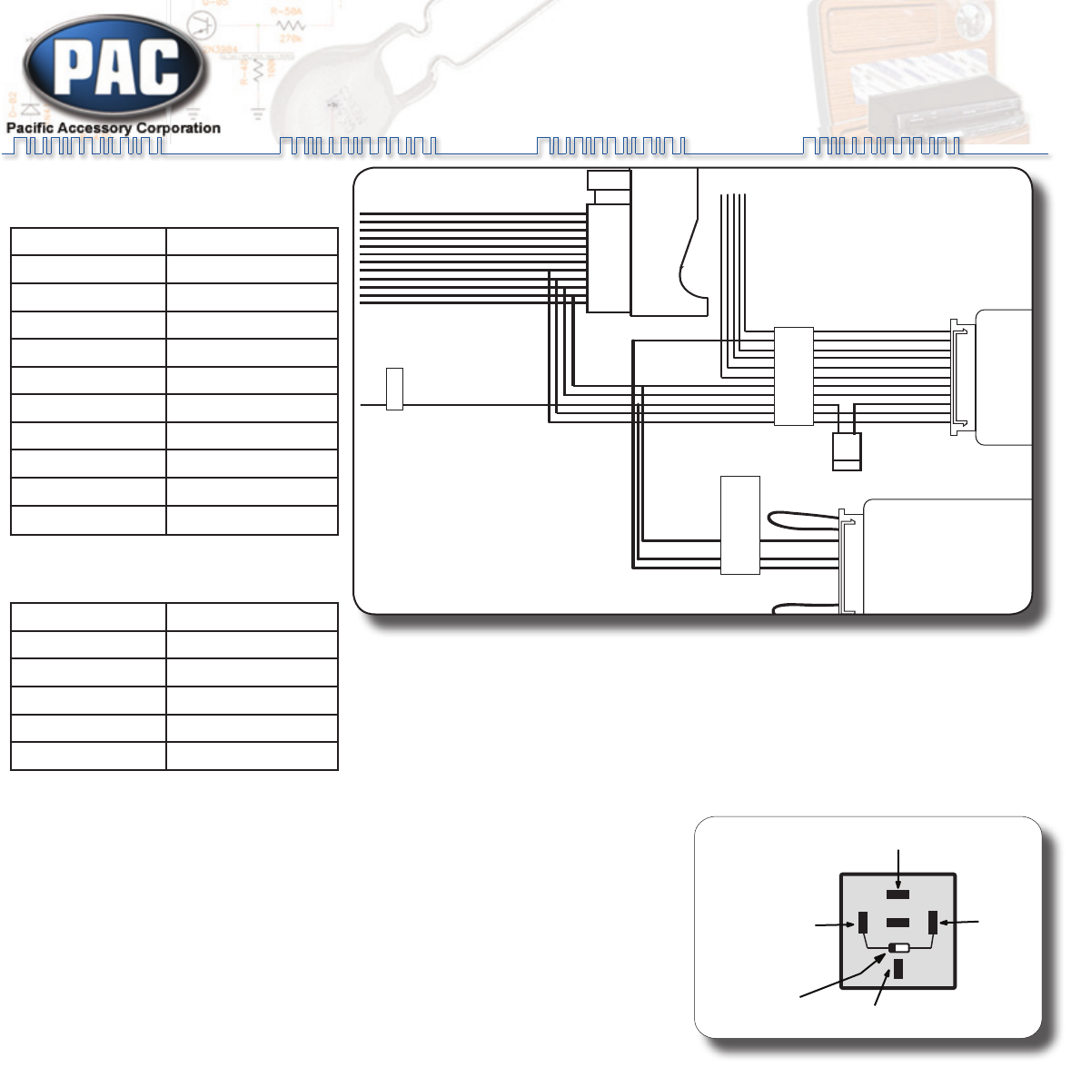
+12v, 1 amp max when key is in the
accessory or ignition position (see g. 1: If more current is needed).
3. 11 pin plug (to CAN INTERFACE):
White/Green - SWC output.1.
Green - Connect this wire to the radio’s reverse input wire only.2.
Orange/White - Connect this wire to the radio’s Illumination input wire only.3.
Violet/White - Connect this wire to the radio’s VSS input wire only.4.
Red/White - Connect this wire to the radio’s parking brake input wire only. 5.
Please Note: The parking brake wire will output a neg (-) trigger at all
times until the vehicle is moving at a speed of approximately 3 mph or
faster.
Note: Do not connect these wires to any circuit other than the aftermarket radio’s wire harness.
4. 11 pin plug (to SWC INTERFACE):
This is a quick connection to a radio specic SWC interface. No additional connections are necessary other than radio
control connections. Plug the radio specic SWC interface in to this connector and program the radio specic SWC
interface for version 2. Do not cut the loops. Refer to the SWC interface instruction manual for the radio specic control
function programming order.
5. Refer to the aftermarket radio’s instruction manual for testing VSS, Reverse, Parking Brake and Illumination outputs.
Fig. 1
(using a SPDT relay)
85 86
30
87
87a
Ground
High Current 12v
(Fused)
12v Acc.
From
Interface
New High
Current Output
Diode 1N4005
or equivelant
9
1
23456
78
1011
Accessory Output
+12volts 1amp max.
9 1
9
1
23456
78
1011
9 1
SWC Interface.
Program for Version 2
Radio Specific Steering
Wheel Control Interface
(Sold Separately)
Program SWC
Interface for Version 2.
CAN INTERFACE
Navigation outputs and
Amplifier Remote Input
See Chart for wire color
descriptions.
Radio Connections. See aside
Chart for color description.
Yellow Battery +12v
Black Ground
Blue Amp Turn On Input
White Front L + input
White / Black Front L - input
Grey Front R + input
Grey / Black Front R - input
Green Rear L + input
Green / Black Rear L - input
Purple Rear R + input
Purple / Black Rear R - input
Radio Connection Chart:
(Read the Installation Notes before making
connections to the provided radio harness)
CAN Interface Connection Chart:
Red Acc. Output (1 amp)
Red / White P.B. Output (-)
Purple / White VSS Output (Pulse)
Orange / White Illum. Output (+)
Green Reverse Output (+)
White / Green SWC Output