


52
3D Assist Mode
The unit is equipped with 3D assist mode to provide support for shooting with a rig-type 3D camera system.
The 3D assist mode has the following functions.
Image input method: SIMULTANEOUS (simultaneous method)R
■
Two types of image, one for the left eye (L) and one for the right eye (R), are input to the two SDI1 and
SDI2 terminals.
In 3D assist mode, the input is fixed to SDI1/SDI2 and the input line cannot be changed.•
An appropriate phase difference with the input signal of SDI2 is one that is up to ±15 µs using the input •
signal of SDI1 as the reference.
If the input signal formats of SDI1 and SDI2 are not identical or only one of the signals is input, the •
screen display will black out.
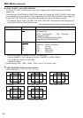
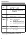
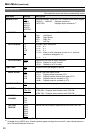
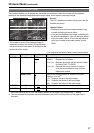
Assist functions
■
Assist Function Name
Screen Indication
Description
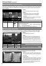
MIRROR Side-by-side Inverts the left and right and top and bottom of SDI2 (R) image
to enable the basic adjustments of a 3D camera to be made.
(Half-mirror type supported)
SHIFT Overlay Shifts SDI2 (R) image horizontally and vertically to enable the
lens axis of the 3D camera to be checked.
COMPARISON Side-by-side Displays a halftone marker on the inside. A subject captured
with only the camera of the L or R can be checked.
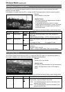
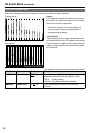
CONVERGENCE
Normal 1
screen display
Switches the L/R images automatically or manually to enable
the convergence point to be checked.
COLOR Overlay Overlays the L/R images on a checkerboard pattern to enable
the brightness or color offset to be checked.
ZOOM FOCUS Side-by-side Enlarges part of an image to enable the focus offset or zoom
offset to be checked.
VERTICAL Side-by-side Displays the horizontal line markers to enable the vertical offset
to be checked.
OVERLAY Overlay Displays the vertical line markers to enable the width of parallax
to be checked.
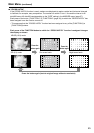
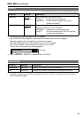
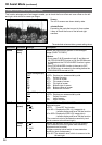
How to switch to 3D assist mode
■
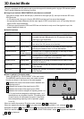
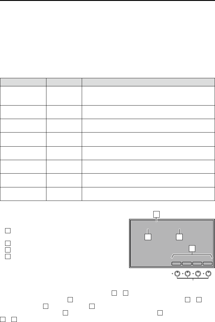
Select [3D ASSIST] in “2D/3D ASSIST” of the main menu.
The MIRROR assist functions starts, and a status screen
like the one shown in the figure on the rights appears.
1 Indicates the name of the assist function selected with
adjusting knob 4.
2 Indicates the format of the signal input to SDI1.
3 Indicates the format of the signal input to SDI2.
4 Indicates the functions assigned to adjusting knobs 1 to
4. For the functions assigned to adjusting knobs 1 to 3,
the definitions vary by assist function. The setting value
of each function is confirmed at the point in time when
the corresponding adjusting knob is operated. (pages
54 to 58)
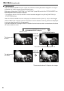
When you switch the mode to 3D assist mode, statuses
1 to 3 are displayed.
When you operate the function of
4 : If you press one of the adjusting knobs 1 to 4, statuses 1 to 3
disappear and status
4 is displayed. Status 4 continues to be displayed until the operation ends.
When you end the operation of
4 : If you press the FUNCTION3 button, status 4 disappears and statuses
1 to 3 are displayed.
3D ASSIST - MIRROR-
SDI1(L): 1080/60i(L) SDI2(R): 1080/60i(R)
MIRROR
-
-
FUNC.
OFF
MIRR
1
2 3
4
Adjusting knob 1 - 4