


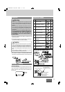


36
CQ-BT5107U
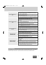
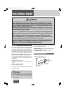
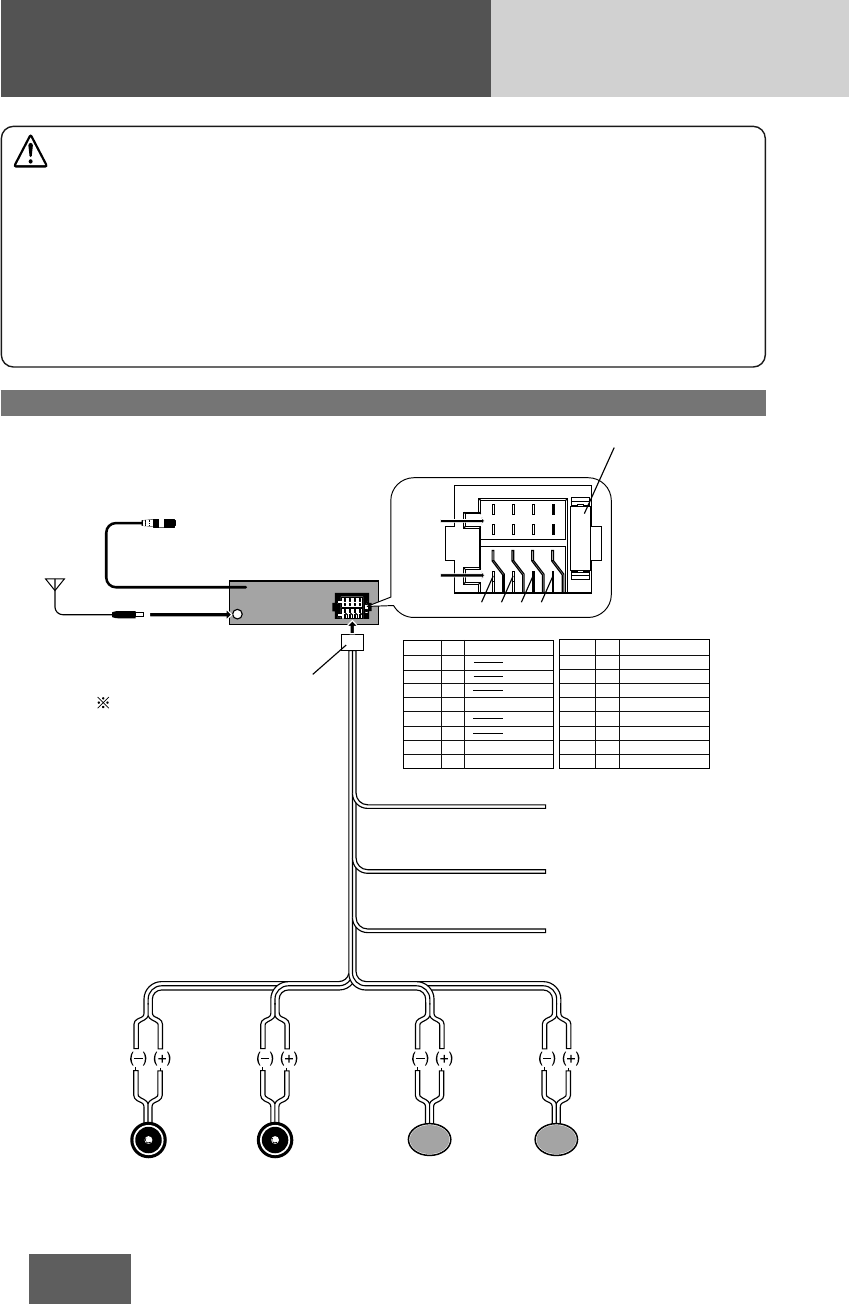
Electrical Connections
Wiring diagram
(Rear Side)
Main Unit
CQ-BT5107U
Antenna
Accessory Power(ACC)
(+12 V DC, negative ground
only)
Ground Lead
(Connect to a clean, bare
metallic part of your vehicle)
Battery Lead
(Connect to vehicle battery)
(Red)
ACC
Ground
(Black)
(Yellow)
Battery
(Violet)
(Violet/Black)(Gray/Black)
(Green)
(Green/Black)(White/Black)
(Gray)
(White)
Left Speaker
(Front)
Right Speaker
(Front)
Left Speaker
(Rear)
Right Speaker
(Rear)
Power Connector
Microphone Input Connector
(Connect to supplied Microphone with Bracket o)
Note: Make sure to wind the attached Adhesive Sponge !0
around the connecting portion for reinforcement. (a page 35)
*Fuse (15 A)
Refer fuse replacement
to your nearest authorized
Panasonic Servicenter.
Do not try fuse
replacement by yourself.
The power connector does not come
along with the unit. If need, please
consult your nearest authorized
Panasonic Servicenter.
Detail of power connector
Cavity FUNCTION PIN FUNCTION
A REAR SP R (+)
A REAR SP R (–)
A FRONT SP R (+)
A FRONT SP R (–)
A FRONT SP L (+)
A
Battery
Ground
FRONT SP L (–)
A REAR SP L (+)
A REAR SP L (–)
ACC
Cavity
B
B
B
B
B
B
B
B
PIN
1
2
3
4
5
6
7
8
1
2
3
4
5
6
7
8
1 3 5 7
1
2468
357
2
4 6 8
Cavity B
Cavity A
Caution
• This wiring information is for experienced technical individual, for safety reason, please your dealer wire this con-
nection.
• This product is designed to operate with a 12 V DC, negative @ ground battery system.
• To prevent damage to the unit, be sure to follow the connection diagram below.
• Do not insert the power connector into the unit until the wiring is completed.
• Be sure to insulate any exposed wires from a possible short-circuit from the vehicle chassis. Bundle all cables and
keep cable terminals free from touching any metal parts.
• Remember, if your vehicle has a drive computer or a navigation computer, the data of its memory maybe erased
when the battery terminals are disconnected.
CQ̲BT5107U 10/11/04 10:30 ページ 36