


1
3
2
4
㧯㧺㧝
㧝㧞㧝㧞
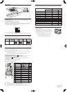
When 1 indoor unit is operated by 2 remote controllers:
Either of the remotes can be set to main/sub.
Wireless Remote Controller
Wired Remote Controller
Receiver
(Sold Separately)
Remote Control Wiring
(Field Supply)
Indoor Unit
Use wiring of AWG#20 – AWG#14 for
fi eld supply.
Use a total wire length of no more than
1300 ft.
(Main)
(Sub)
Warnings about Installation of Receivers
The wireless remote uses a very weak infrared light for its signal, which can result in the signal not
being received because of the following infl uences, so take care in where the unit is installed.
• Inverter or rapid-start type fl uorescent lights. (Models without glow lamps)
• Plasma display or LCD televisions.
• Direct sunlight or other sources of bright light.
Warnings about Installing Remote Controllers
If a remote controller is to be operated from a remote control holder that is hung on a wall, turn
on the lights in the room as well as any electrical appliances and then check to make sure the air
conditioner works with the remote controller in the location where it will be installed. If it works,
continue with installation.
If the air conditioner is to be switched from the main sensor to a remote control sensor, pay attention
to the following when installing.
• Locate where no warm or cold drafts will affect it.
• Locate in a place free from direct sunlight.
• Locate where it will not be affected by any other heat/cold source.
Customer Explanation
Give the Operating Instructions and this manual to the customer after fi nishing the installation.
Use the Operating Instructions to explain to the customer how to use and care for the unit.
Things to remember when wired and wireless remotes are
installed at the same time
Two remote controllers can be used to control the unit if the wireless remote controller is installed at the
same time as the wired remote controller.
(Up to 2 remotes [a wireless remote controller and the wired remote controller] can be installed.)
When using 2 remotes, one or more units can be operated by the remotes.
<Note> When wiring remote controllers, be sure to double-check the terminal numbers of the indoor unit before
connecting them so there are no mistakes in the wiring. (Damage will occur if high voltage [e.g. supply
voltage] is applied.)
<Note> It is not possible to use more than one wireless remote controller with one indoor unit. (A receiver located
separately can be used at the same time.)
<Note> If both a wireless and a wired remote controller are to be installed and used at the same time, one of
them must be set up as the sub remote controller.
If the wired remote controller is to be the sub remote, change the wired remote controller to the sub remote.
If the wireless remote controller is to be the secondary, turn the #3 switch on the wireless receiver (operation
panel) from OFF to ON.
㧯㧺㧝
㧝㧞㧝㧞
If a group of units are to be controlled by 2 remote controllers;
Main/sub remote controllers will work regardless of which indoor unit they are installed to.
Wireless Remote
Controller
Wired Remote
Controller
Use wiring of AWG#20 –
AWG#14 for fi eld supply.
Make the total wire length
when cross-wiring a group
no more than 650 ft.
1st Indoor
Unit
2nd Indoor
Unit
3rd Indoor
Unit
4th Indoor
Unit
(Main)
(Sub)
Cross-wiring Remotes for Group
Control (Field Supply)
DIP Switch 3
CZ-RWSU2U
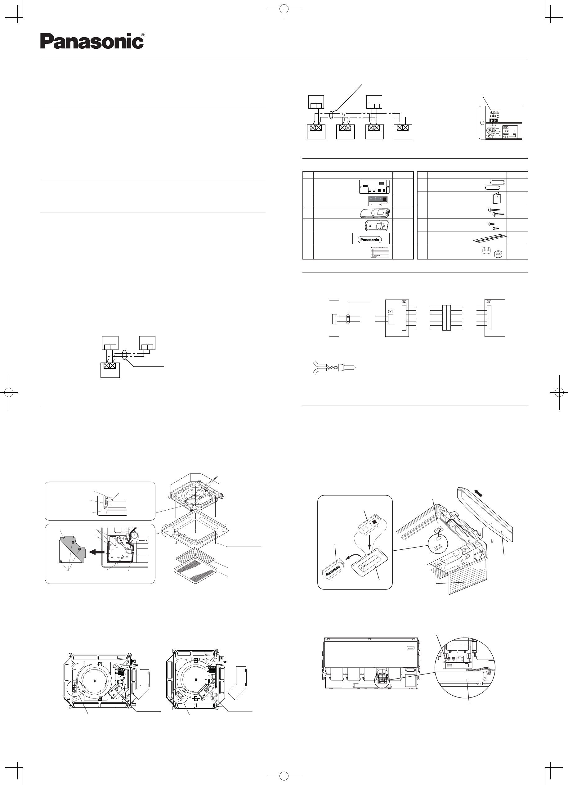
Installing the Display/Operation Panel
4-Way Casette Type
Installing the Display
1 Remove the ceiling panel.
Remove the air-intake grille and air fi lter, disconnect the wiring connector
inside the electrical component box, and then remove the 4 mounting screws.
2 Remove the corner cover behind the mark section. (3 screws)
3 Remove the mark section inside the ceiling panel. (2 screws)
4 Install the display in the location where the mark section was attached. (2 screws)
5 Form the wire to match the panel ribs as shown in FIg. 1.
6 Install the corner cover. (Restrain the wire with the corner cover.)
Fig. 1
Clamp
Panel catch
Screws with washer
Ceiling panel
Air fi lter
Air-intake grille
Wiring connector
Electrical
component box
Ceiling panel
Corner cover
2 screws
Display
3 screws
Wiring
Pass the wiring through
under the shaft.
Installing the Operation Panel
1 Fasten the operation panel to the indoor unit intake port section (electrical component box opposite side) with
the 2 accessory screws.
2 Connect the operation panel 2 wires (WHT, BLK) to the remote control wire (WHT) in the electrical component
box. (For details on wiring, see “Wiring”)
3 Install the ceiling panel.
4 Connect the display and the operation panel with 6P connector (white).
5 Form the wires with vinyl clamps and fasten.
6 Install the wiring connector from the ceiling panel to the connector in the electrical component box of the indoor
unit. After installing the connector, use the clamp on the body of the indoor unit to secure the wiring.
7 Install the air fi lter and air-intake grille.
ATR-IIK224A
TAM TH 0045
ATR-IIK224A
TAM TH 0045
Fig. 2
Operation Panel
Operation Panel
Electrical
component box
Electrical
component box
<Note 1> If the wiring to the operation panel is bundled together with other wiring, such as the incoming line from
the power source, it can cause a malfunction, so avoid doing so.
<Note 2> If something causes the unit’s power source to make noise, it will be necessary to resolve the problem,
such as by installing a noise fi lter.
For more information about wiring or test runs, refer to Wiring the Receiver and Test Run.
Ceiling Type
Installing the Display
1 Remove the side panel.
Open the air intake grille, remove the screw at one place and then remove the side panel by sliding it toward the
front (arrow direction).
2 Remove cover A and cover B.
Insert a standard screwdriver into the recess of cover A to remove cover A and cover B. (When removing the cover,
take care not to scratch the panel.)
3 Remove cover B from cover A.
4 Install the display at cover A.
5 After passing through the lead wires, install cover A and the display at the panel hole. (The protrusion part of cover
A is fi xed with the panel hole.)
6 Bundle the lead wires along with the wiring of the louver motor.
7 Install the side panel.
Display
Cover B
Cover A
Panel
Side Panel
Air intake grille
Fig.3
Installing the Operation Panel
1 Fasten the operating controller to the ceiling panel of the air intake section with the 2 supplied screws.
2 Draw the lead wires into the electrical component box and connect the operating controller 2 wires (WHT, BLK) to
the remote control wires in the electrical component box.
3 Connect the indicator section and the operating controller using the 6P connector in the electrical component box.
Operation Panel
Electrical component box
Fig.4
<Note 1> If the wiring to the operation panel is bundled together with other wiring, such as the incoming line from
the power source, it can cause a malfunction, so avoid doing so.
<Note 2> If something causes the unit’s power source to make noise, it will be necessary to resolve the problem,
such as by installing a noise fi lter.
For more information about wiring or test runs, refer to Wiring the Receiver and Test Run.
Accessories
No. Accessories Quantity
1
Operation Panel
1
2
Display
1
3
Remote Controller 1
4
Remote Control Holder 1
5
Badge 1
6
Label 1
No. Accessories Quantity
7 Dry-cell Batteries 2
8 Operating Instructions 1
9 Truss Self-Tapping Screws 2
10
Pan Head Self-Tapping Screws
4
11
Plastic Clamp
3
12
Spacer
2
Wiring
Wiring Diagram
White
Black
Blue
Yellow
Pink
Red
Gray
Display
Operation Panel
Indoor Unit
Black
Blue
Yellow
Pink
Red
Gray
Black
㹕㸰 㹕㸱
㹕㸯
Relay connector
RC
Connections
Connections
1 Connect W3 from the display with W2 from the operation panel using the relay connector.
Enclosed wire joints
1. Strip the wire to be connected of its sheathing for 35/64 in.
2. Twist the two wires together and crimp the enclosed wire joint.
3. If a special crimping tool is not used, or if the connection is made using solder,
wrap the joint with insulating tape.
W1
INSTALLATION INSTRUCTIONS
Model No. CZ-RWSU2U