


Other Functions
Adjusting initial settings
1 Press SRC/OFF and hold until the unit
turns off.
2 Press SRC/OFF and hold until the clock
appears in the display.
3 Press FUNC to select the initial setting.
After selecting, perform the following proce-
dures to set the initial setting.
Setting the clock
1 Press c or d to select the segment of the clock
display you wish to set.
Hour—Minute
2 Press a or b to put a clock right.
FM (FM tuning step)
The FM tuning step employed by seek tuning can be
switched between 100 kHz, the prese t step, and 50
kHz.
! If seek tuning is performed in 50 kHz steps, sta-
tions may be tuned in imprecisely. Tune in the sta-
tions with manual tuning or use seek tuning
again.
1 Press c or d to select the FM tuning step.
50 (50 kHz)—100 (100 kHz)
AM (AM tuning step)
The AM tuning step can be switched between 9 kHz,
the preset step, and 10 kHz. When using the tuner in
North, Central or South America, reset the tuning
step from 9 kHz (531 kHz to 1602 kHz allowable) to 10
kHz (530 kHz to 1640 kHz allowable).
1 Press c or d to select the AM tuning step.
9 (9 kHz)—10 (10 kHz)
AUX (auxiliary input)
Activate this setting when using an auxiliary device
connected to this unit.
1 Press a or b to turn auxiliary setting on or off.
Displaying the clock
% Press to turn the clock display on or
off.
# The clock display disappears temporarily
when you perform other operations, but the clock
display appears again after 25 seconds.
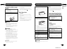
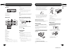
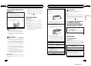
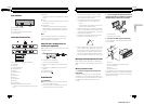
Using an AUX source
1 Insert the stereo mini plug into the
AUX input jack.
2 Press SRC/OFF to select AUX as the
source.
# AUX cannot be selected unless the auxiliary
setting is turned on. For more details, refer to
AUX (auxiliary input) on this page.
En
8
Section
02
Operating this unit
Connections
WARNING
! Use speakers over 50 W (output value) and be-
tween 4 W to 8 W (impedance value). Do not
use 1 W to 3 W speakers for this unit.
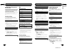
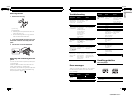
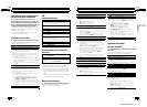
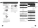
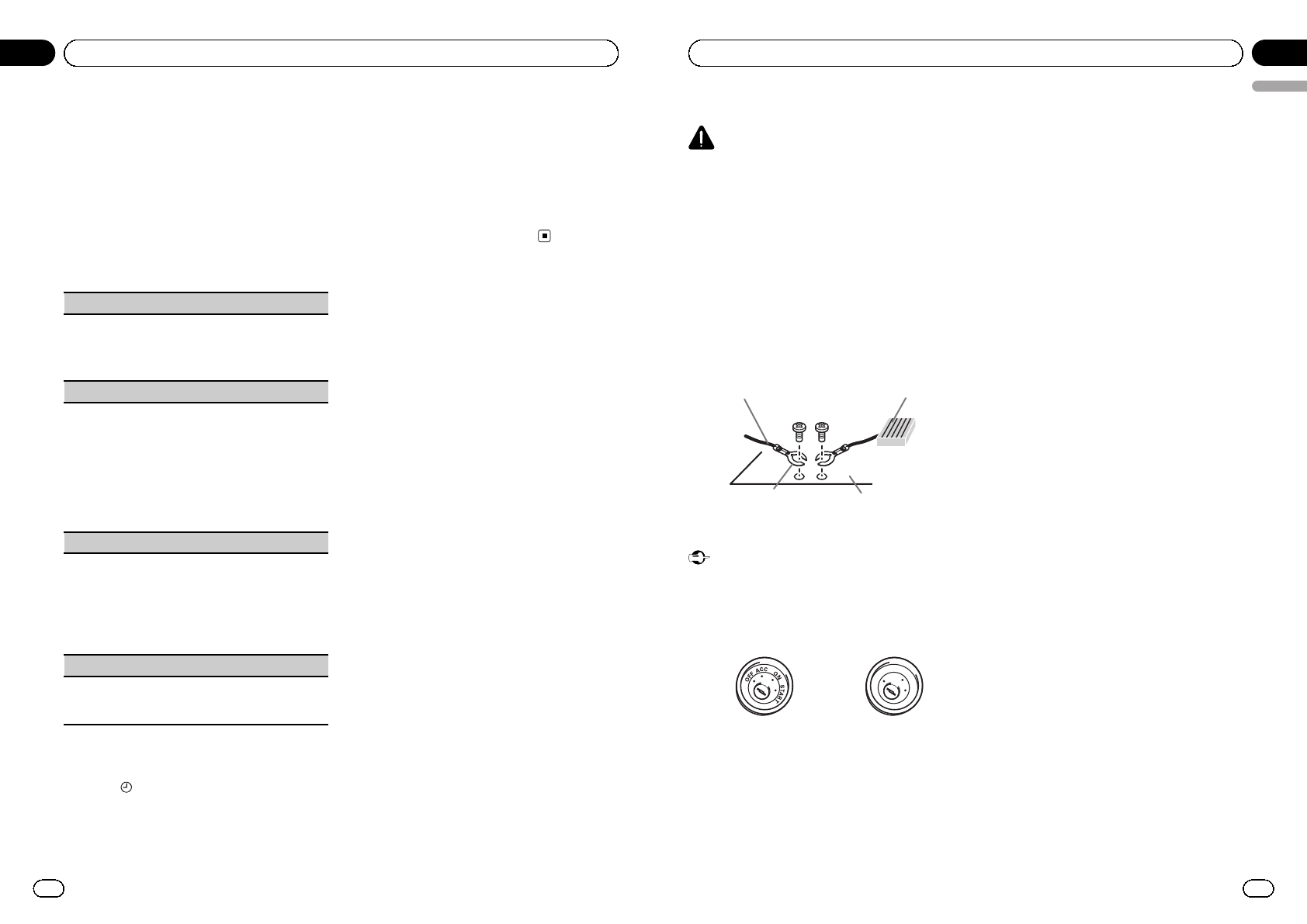
! The black cable is ground. When installing
this unit or power amp (sold separately), make
sure to connect the ground wire first. Ensure
that the ground wire is properly connected to
metal parts of the car’s body. The ground wire
of the power amp and the one of this unit or
any other device must be connected to the car
separately with different screws. If the screw
for the ground wire loosens or falls out, it
could result in fire, generation of smoke or
malfunction.
Ground wire
Metal parts of car’s body
POWER AMP
Other devices
(Another electronic
device in the car)
Important
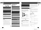
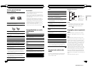
! When installing this unit in a vehicle without
an ACC (accessory) position on the ignition
switch, failure to connect the red cable to the
terminal that detects operation of the ignition
key may result in battery drain.
O
N
S
T
A
R
T
O
F
F
ACC position No ACC position
! Use this unit with a 12-volt battery and nega-
tive grounding only. Failure to do so may result
in a fire or malfunction.
! To prevent a short-circuit, overheating or mal-
function, be sure to follow the directions
below.
— Disconnect the negative terminal of the
battery before installation.
— Secure the wiring with cable clamps or ad-
hesive tape. Wrap adhesive tape around
wiring that comes into contact with metal
parts to protect the wiring.
— Place all cables away from moving parts,
such as the gear shift and seat rails.
— Place all cables away from hot places,
such as near the heater outlet.
— Do not connect the yellow cable to the bat-
tery by passing it through the hole to the
engine compartment.
— Cover any disconnected cable connectors
with insulating tape.
— Do not shorten any cables.
— Never cut the insulation of the power cable
of this unit in order to share the power
with other devices. The current capacity of
the cable is limited.
— Use a fuse of the rating prescribed.
— Never wire the negative speaker cable di-
rectly to ground.
— Never band together negative cables of
multiple speakers.
! When this unit is on, control signals are sent
through the blue/white cable. Connect this
cable to the system remote control of an exter-
nal power amp or the vehicle’s auto-antenna
relay control terminal (max. 300 mA 12 V DC).
If the vehicle is equipped with a glass anten-
na, connect it to the antenna booster power
supply terminal.
! Never connect the blue/white cable to the
power terminal of an external power amp.
Also, never connect it to the power terminal of
the auto antenna. Doing so may result in bat-
tery drain or a malfunction.
En
9
English
Section
03
Installation
<QRD3062-A/N>5