


Black plate (40,1)
WARNING
! Insome countriesor statesthe viewingof images
on adisplay insidea vehicle evenby persons
other thanthe drivermay be illegal.Where such
regulations apply, theymust beobeyed andthis
unit’s DVDfeatures shouldnot beused.
CAUTION
! Donot drill ahole into the engine compart-
ment to connectthe yellow cable of the dis-
play unit tothe vehicle battery. Engine
vibration may eventuallycause the insulation
to fail at thepoint where the wirepasses
from the passengercompartment into the
engine compartment. Takeextra care in se-
curing the wireat this point.
! Makesure thatcables will not interfere with
moving parts of thevehicle, such as the shift
lever, parkingbrake or seat sliding mecha-
nism.
WARNING
! Usespeakers over 50W (output value) and
between 4 Wto 8 W (impedance value).Do
not use 1W to 3 W speakers forthis unit.
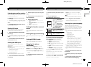
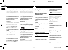
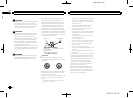
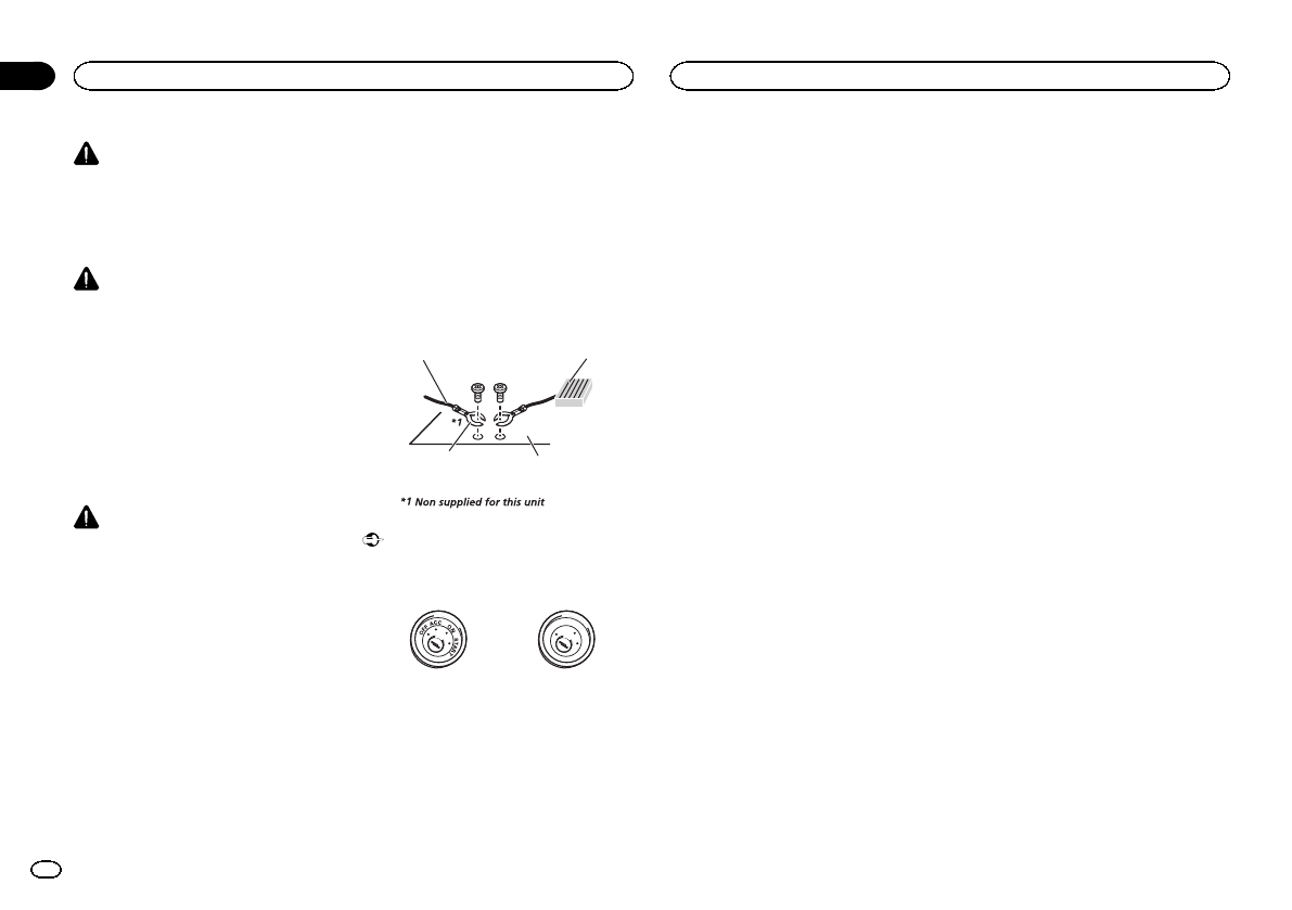
! Theblack cableis ground. When installing
this unit or poweramp (sold separately),
make sure toconnect the ground wire first.
Make sure thatthe ground cable is properly
connected to metalparts of the car body
using a spadeterminal sold commercially.
The ground wireof the power amp and the
one of this unitor any other device mustbe
connected to thecar separately with different
screws. If the screwfor the ground wire loos-
ens or falls out, itcould result in fire, genera-
tion of smokeor malfunction.
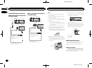
Ground wire
Metal parts of car’s body
POWER AMP
Other devices
(Another electronic
device in the car)
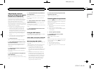
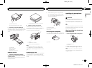
Important
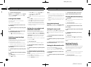
! Thisunit cannot beinstalled in a vehicle
without ACC (accessory) position onthe igni-
tion switch.
O
N
S
T
A
R
T
O
F
F
ACCposition NoACC position
! Usethis unit witha 12-volt battery and nega-
tive grounding only. Failure to doso may re-
sult in afire or malfunction.
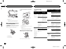
! To prevent a short-circuit, overheatingor mal-
function, be sureto follow the directions
below.
— Disconnectthe negative terminalof thebat-
tery before installation.
— Securethe wiring withcable clampsor adhe-
sive tape.Wrapadhesive tape aroundwiring
that comesinto contactwith metalparts to
protect thewiring.
— Placeall cables awayfrom movingparts,
such asthe shiftlever and seatrails.
— Placeall cables awayfrom hotplaces, such
as nearthe heateroutlet.
— Donot connectthe yellow cableto thebattery
by passingit throughthe holeto the engine
compartment.
— Coverany disconnected cableconnectors
with insulatingtape.
— Donot shorten anycables.
— Nevercut the insulationof thepower cable of
this unitin orderto share thepower with
other devices.The currentcapacity of the
cable islimited.
— Usea fuse ofthe ratingprescribed.
— Never wirethe negativespeaker cabledirectly
to ground.
— Neverband together negativecables ofmulti-
ple speakers.
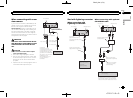
! Whenthis unitis on, control signals aresent
through the blue/whitecable. Connect this
cable to thesystem remote control of anex-
ternal power ampor the vehicle’s auto-anten-
na relay controlterminal (max. 300mA
12VDC). If thevehicle is equipped witha
glass antenna, connectit to the antenna
booster power supplyterminal.
! Neverconnect theblue/white cable to the
power terminal ofan external power amp.
Also, neverconnect it to the powerterminal
of the auto antenna.Doing so may result in
battery drain or a malfunction.
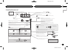
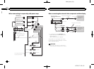
Connection
40
Section
Connection
En
23
<CRD4711-B>40