


Black plate (41,1)
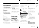
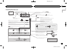
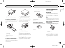
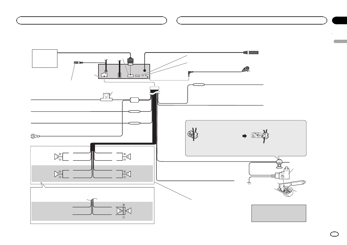
Connecting the power cord
Fuse (10 A)
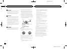
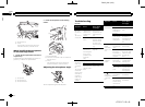
Connection method
1. Clamp the lead.
2. Clamp firmly with
needle-nosed pliers.
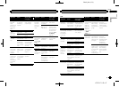
Note:
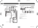
· The position of the parking brake switch depends on the vehicle model. For details,
consult the vehicle Owner’s Manual or dealer.
Yellow/black
If you use an equipment with Mute function, wire this lead to
the Audio Mute lead on that equipment. If not, keep the Audio
Mute lead free of any connections.
Light green
Used to detect the ON/OFF status of the parking
brake. This lead must be connected to the power
supply side of the parking brake switch.
Blue/white
Connect to system control terminal of the power amp or
auto-antenna relay control terminal (max. 300 mA 12 V DC).
Ground side
Power supply side
Parking brake
switch
Yellow
Connect to the constant 12 V supply terminal.
Red
Connect to terminal controlled by ignition switch (12 V DC).
Black (chassis ground)
Connect to a clean, paint-free metal location.
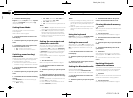
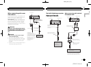
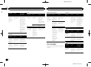
Left Right
Front speaker Front speaker
Rear speaker or
Subwoofer (4 Ω)
White Gray
Gray/blackWhite/black
Green Violet
Green/black Violet/black
With a 2 speaker system, do not connect anything to the speaker leads
that are not connected to speakers.
Note:
· Change the initial setting of this unit. The
subwoofer output of this unit is monaural.
Violet
Violet/black
Not used.
Green
Green/black
When using a subwoofer of 70 W (2 Ω), be sure to connect with Violet and Violet/black leads of this unit.
Do not connect anything to Green and Green/black leads.
Subwoofer (4 Ω)
× 2
Rear speaker or
Subwoofer (4 Ω)
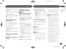
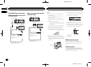
Violet/white
Of the two lead wires connected to the back lamp, connect the one
in which the voltage changes when the gear shift is in the
REVERSE (R) position. This connection enables the unit to
sense whether the car is moving forwards or backwards.
Orange/white
Connect to lighting switch terminal.
Microphone
(Function of AVH-X7500BT)
4 m (13 ft. 1 in.)
Microphone input
(Function of AVH-X7500BT)
This product
Antenna input
AUX jack (3.5 ø)
(AUX IN)
Use a mini plug cable to connect
with auxiliary device.
RGB input
Navigation system
(AVIC-U250(sold
separately))
Please contact your dealer to
inquire about the connectable
navigation unit.
Insert the 26 pin cable in the direction
indicated in the figure.
26 pin cable (Supplied with navigation unit)
Wired remote input
Hard-wired remote control adapter can be connected (sold separately).
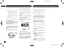
Fuse resistor
Fuse resistor
Fuse resistor
17 cm (6-3/4 in.)
English
Connection
41
Section
Connection
En
23
<CRD4711-B>41