


Piping,
WARNING
Make sure the gas suppliedis the same type listed on the
model rating plate, The inlet gaspressuremust not exceed 14
inches water column [Y2pound per square inch (3o5kPa)]o
The minimum inlet gas pressure"listedon the model rating
plate isfor the purposeoJ'input adjustment.
WARNING
If thegascontrolvalveissubjectedto pressuresexceedingt/_
pound-persquareinch (3.5kPa),thedamageto the gascon-
trolvalvecouldresultin afire or explosionfromleakl'nggas°
WARNING
If themaingaslineshutoff servingall gasappliancesisused,
alsoturn"OFF" thegasateachappliance.Leaveall gasappli-
ancesshutoffuntilthewater heaterinstallationiscomplete°
A gas line of sufficient size must be run to the water
heater. Consult the latest edition of National Fuel Gas
Code ANSI Z223 1, also referred to as NFPA54 and the
gascompany concerning pipe size
There must be:
-A readily accessible manual shut off valve in the gas sup-
ply line serving the water heater, and
-A drip leg (sediment trap) ahead of the gas control valve
to help prevent dirt and foreign materials from entering
the gascontrol valve
-A flexible gasconnector or a ground joint union between
the shutoff valve and control valve to permit servicing of
the unit
Be sure to check all the gas piping for leaks before lighting
the water heater Use a soapy water solution, not a match
or open flame. Rinse off soapy solution and wipe dry
Standard Models are for installation up to 3,300 feet
above sea level.
High Altitude Models are for installation from 3,300 to
5,500 feet above sealevel
If a standard model is installed above 3,300 feet or a high
altitude model is installed above 5,500 feet, the input rat-
ing must be reduced at the rate of 4 percent for each
1,000 feet above sea level. Contact your local Sears
Service Center or gas utility for further information
WARNING
I The appliance and its gasconnection mustbe leak test-
ed bef(_replacing the appliance in operation.
........... WARNING. ......
The appliance and its individual shutoff valve must be discon-
nected from the gassupply piping systemduring any pressure
testing of that systemat test pressuresin excessof'h pound
per square inch (3_5kPa).
The appliance must be isolated from the gassupplypiping sys-
tem by closingits individual manual shutoff valve during any
pressuretesting of the gas supply piping system at test pres-
sures equal to or lessthan =/2poundper squareinch (3.5kPa).
WARNING
Use pipejoint compoundor teflon tape marked as being
resistantto theaction of petroleum[Propane(LP,)] gases_
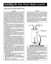
SEDIMENT TRAP
A sediment trap shall be installed as close to the inlet of
the water heater as practical at the time of water heater
installation The sediment trap shall be either a tee fitting
with a capped nipple in the bottom outlet or other device
recognized as an effective sediment trap. If a tee fitting is
used, it shall be installed in conformance with one of the
methods of installation shown below.
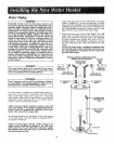
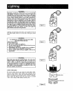
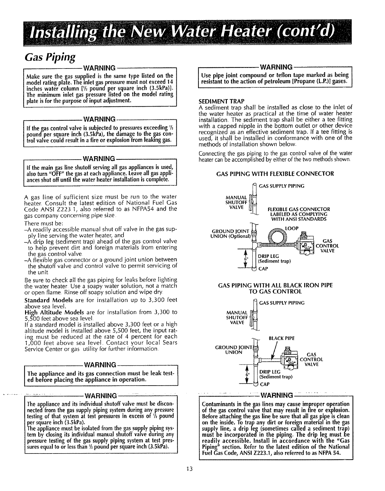
Connectingthe gaspiping to the gascontrol valveof the water
heatercan be accomplishedbyeitherof thetwo methodsshown
GAS PIPING WITH FLEXIBLE CONNECTOR
_._ GAS SUPPLY PIPING
MANUAL J_1'
SHUTOFFli_
VALVE
_ FLEXIBLE GAS CONNECTOR
LABELEDASCOMPLYING
WITHANSISTANDARDS
GROUND
UNION (Optional)
LOOP
GAS
CONTROL
VALVE
GAS PIPING WITH ALLBLACK IRON PIPE
TO GAS CONTROL
MANUAL _GAS SUPPLY
SHUTOFF
VALVE
PIPING
_[_ BLACKPIPE
GROUND JOINTi_ /
UNION __
GAS
CONTROL
VALVE
......... WARNING ............. -
Contaminants in the gas lines may cause improper operation
of the gas control valve that may result in fire or explosion.
Before attaching the gasline be sure that all gaspipe is clean
on the inside. To trap any dirt or foreign material in the gas
supply line, a drip [eg (sometimes caJled a sediment trap)
must be incorporate([ in the pipings"The drip. leg must,be
readily accessible, install in accordance with the Gas
Piping_' section. Refer to the latest edition of the National
Fuel Gas Code, ANSI Z223_1, alsoreferred to as NFPA54.
13