


E
16
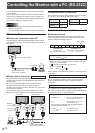
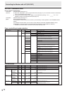
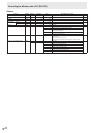
RS-232C command table
How to read the command table
Command: Command eld (See page 12.)
Direction: W When the “Parameter” is set in the parameter eld (see page 12), the command functions as described
under “Control/Response Contents”.
R The returned value indicated under “Reply” can be obtained by setting “????”, “
?” or “???+”
(repeater control) in the parameter eld (see page 12).
Parameter: Parameter eld (See page 12.)
Reply: Response (Returned value)
*: “A” indicates a command which can be used in power standby mode regardless of the STANDBY MODE
setting.
“B” indicates command which can be used in power standby mode when STANDBY MODE is set to
STANDARD. (It cannot be used in the power standby mode when LOW POWER is selected.)
“–” indicates a command which cannot be used in power standby mode.
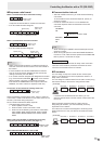
Power control/Input mode selection
Function
Command Direction
Parameter Reply Control/Response contents *
POWER CONTROL POWR W 0
Switches to standby mode.
A
1 Returns from standby mode.
R 0 Standby mode
1 Normal mode
2 Input signal waiting mode
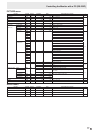
INPUT MODE SELECTION INPS W 0 Toggle change for input mode. Terminals not selected in DVI SELECT/
BNC SELECT/HDMI SELECT cannot be selected.
B
1 PC1 DVI-D
“ERR” when AV1 DVI-D is selected for DVI SELECT.
2 PC3 D-SUB
3 AV3 COMPONENT
“ERR” when PC4 RGB is selected for BNC SELECT.
4 AV5 VIDEO
6 PC4 RGB
“ERR” when AV3 COMPONENT is selected for BNC SELECT.
7 AV1 DVI-D
“ERR” when PC1 DVI-D is selected for DVI SELECT.
8 AV4 S-VIDEO
9 AV2 HDMI
“ERR” when PC2 HDMI is selected for HDMI SELECT.
10 PC2 HDMI
“ERR” when AV2 HDMI is selected for HDMI SELECT.
R 1 PC1 DVI-D
A
2 PC3 D-SUB
3 AV3 COMPONENT
4 AV5 VIDEO
6 PC4 RGB
7 AV1 DVI-D
8 AV4 S-VIDEO
9 AV2 HDMI
10 PC2 HDMI
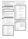
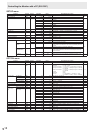
SCREEN menu
Function
Command Direction
Parameter Reply Control/Response contents *
AUTO ASNC W 1 When the input mode is PC3, PC4.
-
CLOCK CLCK WR 0-1200 0-1200 When the input mode is PC3, PC4. Varies depending on the signal.
PHASE PHSE WR 0-63 0-63 When the input mode is PC3, PC4.
POSITIONING POSITION OF
THE LONGEST
DIRECTION
HPOS WR 0-100 0-100 0-800 on PC3/PC4.
Varies depending on the signal.
POSITION OF
THE SHORTEST
DIRECTION
VPOS WR 0-100 0-100 0-200 on PC3/PC4.
Varies depending on the signal.
SIZE POSITION OF
THE LONGEST
DIRECTION
HSIZ WR 0-100 0-100
POSITION OF
THE SHORTEST
DIRECTION
VSIZ WR 0-100 0-100
RESOLUTION H-RESOLUTION HRES WR 300-1920 300-1920 When the input mode is PC3, PC4.
Only even numbers are valid for parameters.
Varies depending on the signal.
V-RESOLUTION VRES WR 200-1200 200-1200
RESET ARST W 1
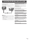
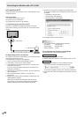
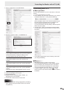
Controlling the Monitor with a PC (RS-232C)