


E
7
n
SETUP
OSD H-POSITION
Adjusts the horizontal display position of menu screen.
OSD V-POSITION
Adjusts the vertical display position of menu screen.
LANGUAGE
Sets the display language for the menu screen.
HDMI AUTO VIEW
When ON is selected, the screen size is adjusted
automatically according to the screen size control signal
included in the video signal input from the AV2 input terminal.
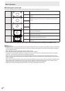
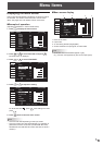
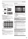
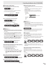
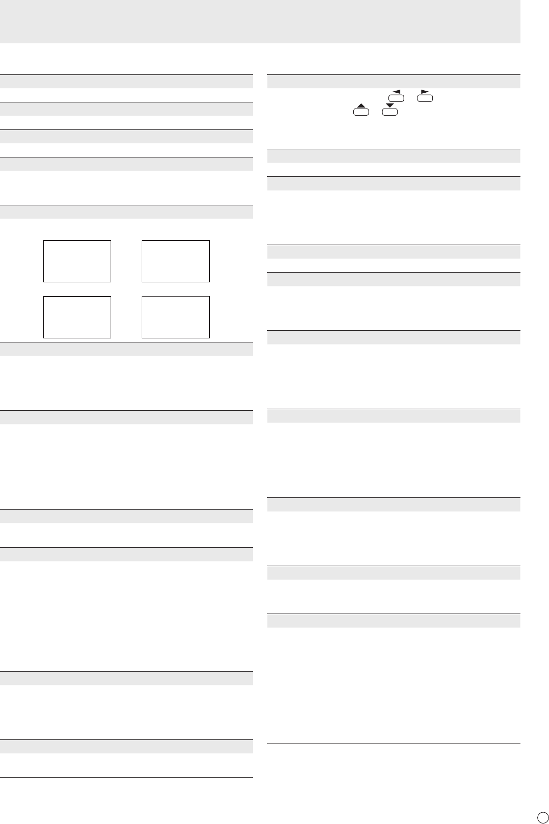
PICTURE FLIP
A picture ips to appear.
STANDARD MIRROR
ROTATE UPSIDE DOWN
ABC
ABC
ABC
ABC
POWER ON DELAY
You can delay the screen display after the monitor is turned
on. The period can be set up to 60 seconds in units of one
second. When this function is activated, the power LED
ashes (at approx. 1 second interval) in orange. This function
is disabled when 0 is specied.
STANDBY MODE
When STANDARD is selected, startup time from standby
mode is reduced. Note, however that, more power will be
consumed in standby mode.
When LOW POWER is selected, current consumption
is reduced while the monitor is in standby mode. Note,
however, that the startup time from standby mode becomes
longer. Also, certain RS-232C commands cannot be used in
standby mode. (See page 16.)
RS-232C/LAN SELECT
Selects the method with which to control the monitor from
the computer.
RS-232C/LAN COMMAND
Set the return value for the RS-232C command.
Normally, you do not need to change this setting from
NORMAL.
NORMAL ...... The end code of the return value is CR+LF.
MODE1 ......... The end code of the return value is CR only.
MODE2 ......... The length of the return value is xed to 4
digits. The end code is CR only.
When the return value has 1 to 3 digits, the
empty digit(s) from the left is lled with a
one-byte space(s).
ID No. SET
Assigns ID numbers to monitors connected in a daisy chain
(see page 13), using RS-232 cables.
The numbers 1 to 255 are available for ID numbers.
If “0” is set, the system regards this as the state where no ID
number is set.
LAN SETUP
Congures the settings to control the monitor from the
computer via LAN. (See page 21.)
n
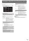
OPTION
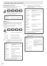
DATE/TIME SETTING
Set the date and time. Press
or
to select the date
and time, and press
or
to change the numerical
values.
Set the date in “Year/Month/Day” order.
Set the time on a 24-hour basis.
SCHEDULE (See page 9.)
You can set the time to switch the monitor on and off.
INPUT SELECT
DVI SELECT ....... Selects the input mode to be used.
BNC SELECT .....Selects the input mode to be used.
HDMI SELECT ... Selects the input mode to be used.
HDMI AUDIO SELECT
.. Selects a terminal to which audio signals
are input in PC2/AV2 mode.
QUICK SHOOT
Reduces the visual lag inherent in fast-motion scenes.
AUDIO OUTPUT
Sets the volume of sound output from the PC/AV audio
output terminals.
VARIABLE .......... You can adjust the volume using VOLUME.
FIXED .................Fixes the sounds.
INPUT SIGNAL (PC3/PC4)
If a computer connected to the PC3/PC4 input terminal
outputs any of the following resolutions, make a selection
from the following options.
480 LINES .......... AUTO, 640x480 or 848x480
768 LINES ..........AUTO, 1024x768, 1280x768, or 1360x768
1050 LINES ........1400x1050 or 1680x1050
SCAN MODE (AV input)
Sets the scan mode used for AV mode input.
MODE1 ............... Over-scan display
MODE2 ...............Under-scan display
MODE3 ............... Under-scan display when the input signal
is 1080i/p. Otherwise, over-scan display
*
Even when MODE1 is selected, under-scan display is used when
the input signal is 1080i/p and the screen size is Dot by Dot.
SELF ADJUST
On a PC3/PC4 screen, specify whether to perform screen
adjustment automatically or not. When ON is selected, the
screen is automatically adjusted when its resolution is 800
x 600 or higher and the timing of input signals changes.
“ADJUSTING” appears on the screen during the adjustment.
POWER MANAGEMENT
POWER MANAGEMENT determines whether or not to
switch modes from no signal to the input signal standby
mode when the PC screen is displayed.
AUTO INPUT CHANGE
Specify whether to change inputs automatically. When ON is
selected and no signal is present in the selected input mode,
AUTO INPUT CHANGE automatically changes the selected
mode to another mode where a video signal is present.
When video signals exist in multiple input modes, the
switching priority is as follows:
PC1, PC2, PC3, PC4, AV1, AV2, AV3, AV4 and AV5.
(Input mode switching may take 15 seconds or more,
depending on the connected equipment. Input signals
may not be detected properly and a priority may change,
depending on the connected equipment or video signals.)
Menu Items