


9
E
n
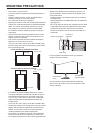
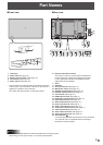
Front view
6
7
45
8824
10
11 12 13 14 15 16 17 18 19 20 21
9
22
23
23
4
5
*
1
Guideline
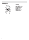
Part Names
n
Rear view
Caution
• Consult your SHARP dealer for attachment/detachment of optional parts.
• When lifting or moving the monitor, do not hold by the speakers.
1. LCD panel
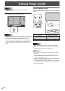
2. Power LED (See page 16.)
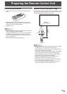
3. Remote control sensor (See page 15.)
4. Input switch (See page 18.)
5. Power switch (See page 16.)
* The Input switch and Power switch are located on the back
of the monitor. Use the position of the slot on the front as a
guideline for operation of the switches.
(The switch with the protrusion is the Power switch.)
6. Optional attachment section
This section is used to connect optional hardware for
function expansion. Offering this attachment location
is not a guarantee that future compatible hardware
attachments will be released.
7. Vents
8. Speakers
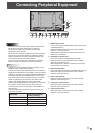
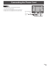
9. AC input terminal (See page 13.)
10. Main power switch (See page 16.)
11. RS-232C output terminal (See page 12.)
12. RS-232C input terminal (See page 12.)
13. LAN terminal (See page 12.)
14. HDMI input terminal (See page 11.)
15. DisplayPort input terminal (See page 11.)
16. DVI-D input terminal (See page 11.)
17. DVI-D output terminal (See page 12.)
18. D-sub input terminal (See page 11.)
19. Audio1 input terminal (See page 12.)
20. Component input terminals (See page 11.)
21. Video input terminal (See page 11.)
22. Audio output terminals (See page 12.)
23. Audio2 input terminals (See page 12.)
24. Anti-theft hole (
)
A commercially available anti-theft lock can be connected.
The anti-theft hole is compatible with the Kensington
MicroSaver Security System.