


36
E
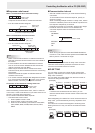
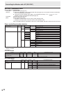
RS-232C command table
How to read the command table
Command: Command eld (See page 32.)
Direction: W When the “Parameter” is set in the parameter eld (see page 32), the command functions as described
under “Control/Response Contents”.
R The returned value indicated under “Reply” can be obtained by setting “????”, “
?” or “???+”
(repeater control) in the parameter eld (see page 32).
Parameter: Parameter eld (See page 32.)
Reply: Response (Returned value)
* : “○” indicates a command which can be used in power standby mode.
“–” indicates a command which cannot be used in power standby mode.
(When STANDBY MODE is STANDARD. When set to LOW POWER, RS-232C commands cannot be used.)
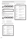
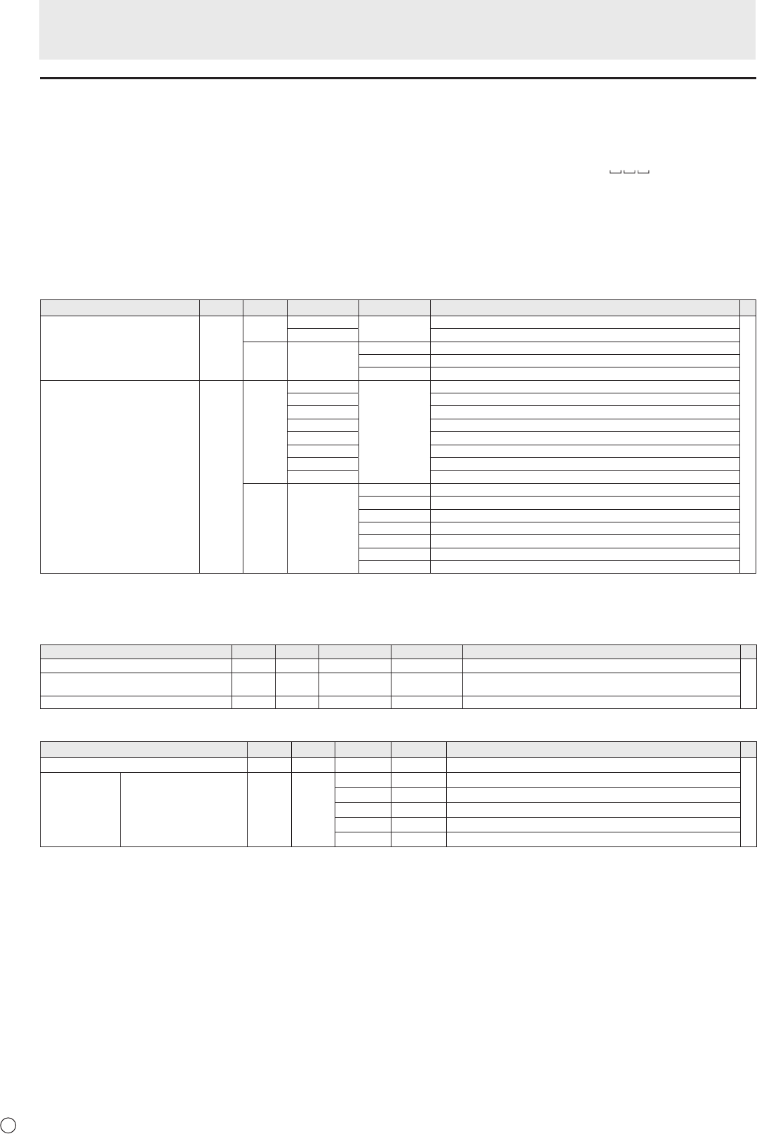
Power control/Input mode selection
Function
Command Direction
Parameter Reply Control/Response contents *
POWER CONTROL POWR W 0
Switches to standby mode.
○
1 Returns from standby mode.
R 0 Standby mode
1 Normal mode
2 Input signal waiting mode
INPUT MODE SELECTION INPS W 0 Toggle change for input mode.
1 DVI-D
2 D-SUB[RGB]
3 D-SUB[COMPONENT]
4 D-SUB[VIDEO]
9 HDMI[AV]
10 HDMI[PC]
11 USB
R 1 DVI-D
2 D-SUB[RGB]
3 D-SUB[COMPONENT]
4 D-SUB[VIDEO]
9 HDMI[AV]
10 HDMI[PC]
11 USB*
* If power standby mode is entered when the input mode is USB, the input terminal that was used prior to switching to USB will
respond, not USB.
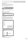
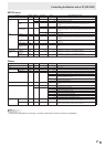
SCREEN menu
Function
Command Direction
Parameter Reply Control/Response contents *
SIZE (DVI-D, HDMI[PC], D-SUB[RGB]) WIDE WR 1-3 1-3 1: WIDE, 2: NORMAL, 3: Dot by Dot
-
SIZE (HDMI[AV], D-SUB[COMPONENT],
D-SUB[VIDEO], USB)
WIDE WR 1, 4, 5 1, 4, 5 1: WIDE, 4: NORMAL, 5: Dot by Dot
AUTO ASNC W 1 When the input mode is D-SUB.
PICTURE menu
Function
Command Direction
Parameter Reply Control/Response contents *
BRIGHT VLMP WR 0-31 0-31
○
COLOR
ADJUSTMENT
COLOR MODE BMOD WR 0 0 STD
2 2 VIVID
3 3 sRGB (When the input mode is DVI-D, D-SUB[RGB], HDMI[PC])
4 4 HIGH ILLUMINANCE
5 5 USB
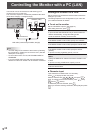
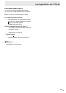
Controlling the Monitor with a PC (RS-232C)