Notches in
skew plate
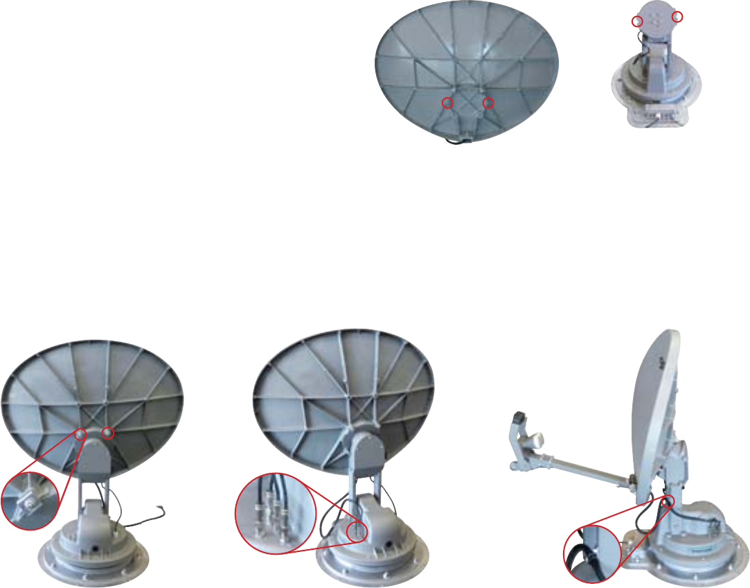
FIGURE 1. Anchor posts and notches to align
Anchor posts
in reflector
FIGURE 2. Installing reflector, LNBF, and feed arm. A, Reflector held on skew plate with clamps. B, Coax cables connected. C, P-clamp on lift arm.
CBA
+
+
+
Installing the Reflector, LNBF, & Feed Arm
Note that the reflector, LNBF, and feed arm are packaged separately as SKA-733.
1. Press and hold “POWER” for two seconds to turn on the interface box. Wait until the interface box finishes
“connecting to antenna.” The TRAV’LER
®
antenna may enter the search routine after ten seconds. Pay attention to
the pinch points as the antenna raises!
2. Wait until the antenna has at least raised to a position in which the lift arms are perpendicular to the roof. Then, press
“POWER” and “SELECT” at the same time. The antenna should stop moving.
3. Unplug the interface box.
4. Insert the two longer screws into the top two holes in the front of the reflector.
5. Slide a wedge-shaped clamp onto each screw sticking out the back of the reflector.
6. Thread a nut onto each screw; make sure the nut is tight to keep the clamp from falling.
7. Align the two anchor posts on the back of
the reflector with the two notches in the skew
plate (see fig. 1). Then, set the reflector on the
skew plate; the reflector should be positioned
with the LNB arm at the bottom of the plate.
Carefully use the clamps on the back of the
reflector to hold the reflector in place (see
fig. 2A); make sure that the thicker part of the
clamp is to the outside of the reflector.
8. Once the top screws and clamps are in place, install the lower screws and clamps.
9. With the bracket mounted securely, connect the four coax cables to the mount (see fig. 2B).
10. Locate the cable tie on the coax cables that you just connected to the mount. Place the p-clamp on the cables so that
it is just below this cable tie. If the cable tie is missing, install the clamp 14” from the end of the connectors.
11. Carefully screw this clamp to the front of the lift arm using the provided
5
/
16
” screw (see fig. 2C). Warning: Be careful
not to strip out the hole for the
5
/
16
” screw when you replace the clamp holding the coax cables to the arm. Do not
use a power tool. Do not overtighten this screw.
12. Plug in the interface box.
13. Press and hold “POWER” for two seconds to turn on the interface box. Press the Power button again to stow the antenna.
2452259


