


A65/75/75P Plus Circuit Description
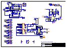
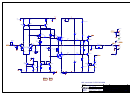
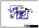
PSU
In order get the output devices to turn fully on and achieve the
greatest efficiency, an auxiliary rail is formed from a charge pump
driven by the main AC outputs from the transformer. C304,305 &
D301,302 charge on alternate cycles. In the other cycle the charge
on C304,305 is pumped into C310,311 respectively. This creates a
voltage much greater than the standard rails, but with low regulation
and high ripple. This is then regulated to 38V via emitter followers
Q300,302,303,305 from a zener stabilized voltage (D304,305)
The Pre-amp ±15V supply comes from linear regulators Z300,301.
The transformer is a dual voltage unit, the required voltage being
selected by which fuse holder is fitted with the appropriate fuse. If an
alternative to 115V or 230V is required then a different transformer
is fitted. The secondary is centre tapped for the main rails, but a
separate winding is added for the uC supply.
The star ground point SP300 is not a component on the PCB and is
on the schematic only for layout purposes.
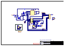
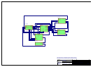
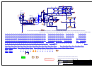
Pre-amp
The direct signal path (line in, tone controls defeated) consists of a
single op-amp gain stage, buffering the j-fet input multiplexers and
Tape Monitor and AV switches. The selected input is AC coupled to
the op-amp, the output is DC to the Pre-out, via a j-fet "pre-mute"
switch. This switch is controlled by the uC in such a way that when
ever the output relay changes state signal is removed from the power
amplifier (A65/75).
The MM phono stage (by passable A75 only, SW100) is opamp
based. The circuit is AC coupled to give RIAA/IEC low frequency
response. The cartridge is loaded by R100,101,C119,120. The 1kHz
gain is 56dB, and RIAA eq set by
R110,112,111,113,C127,129,128,130.
Each line input has static protection afforded by the back to back
diodes (e.g. D101,103), and RF filtering is set by R118,C134 etc.
The selected input is buffered for Tape output by Z104 set as a
follower. The output resistor is inside the feedback loop so to keep
the output impedance low and short protection is catered for.
C121,122 maintain stability into capacitive loads.
From the tape monitor switch (Z105) onwards the signal is AC
coupled (C151,152). From there the signal is fed to the tone controls.
These consist of two stages: Balance and buffer (Z160), and
Bass/Treble Z161. The output of this stage is again AC coupled.
Switch SW162 selects whether the tone adjusted signal or a direct
signal reaches the gain section. In the A75 Z164 can be used to
bypass the volume control when AV input is selected. This fixes the
gain to allow an external AV processor to control the volume setting.
The gain stage (Z163) has a gain of 2.2, and the same low impedance
output arrangement as the Tape output. The signal from this stage to
the Pre- amp outputs and the Power amp input is controlled by a
pre-mute (Z171). This removes thumps and clicks, and in the case of
the Power amp relay changing state, removes signal so arcing will
not take place.
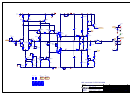
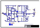
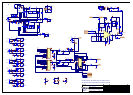
Power Amplifier
The new topology is a high gain voltage feedback design, with a
bipolar output stage. Its signal path is designed to be fully
symmetrical, despite not having a symmetrical circuit (symmetrical
rail to rail). This is achieved with a new dual differential input gain
block, where the input differential sees a symmetrical active load
(Q600,601,700,701) before driving the second voltage amplification
stage (VAS) differential (Q603,604,703,704). This could be
described as two Wilson mirrors with their bases clamped together.
The second differential also has an active load of a more traditional
mirror (Q610,611,710,711), and this gives a push pull signal to the
input of the output stage, improving on the traditional single ended
current source of the often called "blameless" topology.
The input pair (Q606,607,618,619,706,707,718,719) are in a
Darlington configuration to lower input current offset which in turn
will lower DC offset at the output, as the impedances seen on the
input nodes are necessarily high for the wide bandwidth required.
The output stage is a simple bipolar darlington (Q614,615,714,715).
However, the devices used are Darlington devices with integral
diodes. This means the bias temperature compensation is part of the
output device enabling smaller number of devices, no extra devices
on the heatsink (vital for this mechanical layout) and more consistent
temperature compensation of bias. Also the resistors are also
integral, saving a large amount of PCB real estate and hand insertion
cost, while also able to be used as bias set test points and protection
sensing.
Due to the decreased efficiency of this type of output stage over the
previous bootstrapped Mosfet output, a separate set of rails is
required for the VAS stage in order to saturate the output transistors.
The operation of this is outlined in the Power supply section.
However, these rails are individually regulated for each channel to
decrease power supply crosstalk.
The protection of the output stage is taken care of by a proprietary IC
(Z101). This takes care of the switch on delay (R150,C149), DC
offset (R102,103,C147), Thermal trip (TH100), and safe operating
area.
The safe operating area is monitored by a network which
compensates for the voltage across the output devices, current
through them, and duration of power (R627,606,625,605,C617 &
symmetrical associated components) and this is sent to the protection
IC via (Q605,612,613,616,617,712,713,716,717).
The output of the protection IC is sent to the micro controller (uC) to
signal the output relay (RLY1) status. Also, for output muting
purposes, the uC can switch the relay via Q100.
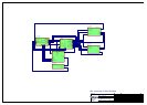
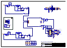
Input Selection
The uC controls the operation of the unit. IR commands are received
from RX900 on a break-off PCB found on the front panel and fed via
LK900/LK903 3-way ribbon. On power on/off the current state of
the pre-amp switching stored in an EEPROM Z906. The input
switching is 5V logic level and is direct from the uC to the DPDT
analogue switches in the case of Tape Monitor (Z105), AV
(Z164,A75 only), Pre-mute (Z171) and Mute Q100. The source
selector is achieved by 8 way analogue multiplexors (Z102,103) and
the control signals are decoded from the uC from MUX1,2,3 by
Z907 which also drives the appropriate front panel LED. The input
selection is set by the remote control or the rotary encoder on the
front panel display PCB. Tape monitor and AV mode(A75 only) is
set by SW900.
Volume Control
The volume control is a motorized manual type, where the signals
are routed through the 8-way ribbon LK189. The motor drive comes
from Z905, which is a logic level controllable motor driver. It has its
own unregulated PSU (D907,C920),and the speed of the volume
knob is dictated by the REF pin. The circuit (Q900,R905,901,C901)
allows the speed to vary from just above stall to full as the volume
control button is depressed on the remote.
SIM Module
The connector PL161 (P75 only) allows the fitting of the ARCAM
SIM module. In order to allow this to operate LK172 & LK173 must
be removed. This will allow 12V trigger signals to operate the P75.
Headphones
The Speaker outputs (SK600,700) are connected to the headphone
socket (SK162) via an 8-way ribbon LK170,171. The output is
attenuated by a resistor network R161,162,236,237. The Relay drive
is fed through the headphone socket's switch (HPSW1,2) so that
when headphones are inserted the speakers are disconnected. Switch
SW163 allows the separate switching of the second speaker
terminals on SK600,700.