


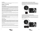
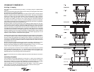

bi-wire connections to the crossover network
connections to the woofer and tweeter are the same as the normal wiring method. Connect the
amplifier to the tweeter to the terminals marked tweeter input. Connect the woofer amplifier to
the woofer input terminals with another run of wire.
Important note - you must cut the jumpers that connect the low frequency and high frequency
sections of the crossover. See diagram . Failing to cut these jumpers could cause damage to the
amplifiers or the crossover.
for biamp operation cut these jumpers
7
14
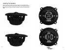
midrange contour
The two position switch labeled car / demo adjusts the frequency response of the midrange
driver. The car position is optimized for in car off axis listening. The demo position offers flat
frequency response when the speakers are able to be placed on axis to the listener. This control
will effect the presence or forwardness of the sound stage. You can experiment with both
positions and set to your preference.
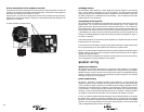
connections to the amplifier
The 3-series crossover is supplied with a removable screw type connector. Strip the wire from the
amplifier about 1/4" from the end and insert into the connector input + and - positions and
tighten the set screws. Strip the wire from the woofer and insert into the + and - positions for
the crossover woofer output. Follow the same procedure for the connection to the tweeter. The
3-series passive crossover has two sets of input terminals, this allows the system to be bi-wired
or bi-amplified. If you select to use one of these wiring schemes you must cut the jumpers in the
crossover to electrically separate the high-pass and low-pass sections (see diagram on page 14
for location of jumpers).
To bi-amplify the system you will need two stereo amplifiers (or 4 amplifier channels) one for the
tweeters and one for the woofers.
If you choose to bi-wire the system, connect the high-pass terminals to the amplifier and connect
the low-pass terminals to the same amplifier with another set of speaker wires.
Be sure to connect the positive crossover terminals to the positive speaker terminals and positive
amplifier terminals, also ensure that the negative crossover terminals connect to the negative
amplifier and speaker terminals.
Once all of the wires are attached to the connector and the crossover is mounted, the connector
can be plugged into its mating receptacle on the crossover.
speaker wiring
speaker wire selection
Use insulated two-conductor stranded wire to connect the 3-series crossover to the speakers
and amplifier. The size of the wire can have an audible effect of the performance of the system.
Standard 18 gauge “zip cord” will work, but can result in lower output or unpredictable frequency
response. For wire runs of 50 feet or less, we recommend 16 gauge or larger wire. The crossover
connector will accept up to 14 gauge wire.
polarity and phasing
The polarity - the positive / negative orientation of the connections - for every speaker and
amplifier connection must be consistent so all the speakers will be in phase. When the polarity
of one connection is reversed, bass output is reduced and stereo imaging is degraded. All wire
is marked so you can identify the two conductors. There may be ribs or a stripe on the insulation
of one conductor. Or the wire may have clear insulation with different color conductors (copper
and silver). Or there may be polarity indications printed on the insulation. Identify the positive
and negative conductors and be consistent with every speaker and amplifier connection.
If one or more pairs of amplifier channels are bridged, there are special methods for connecting
the speaker wires. Instead of connecting the speaker wires to a positive (red) and negative
(black) set of terminals, the speaker wires are connected the positive terminals of the bridged
channels. Of course, proper polarity of the connections is still important, so one of the terminals
must be designated as positive and one as negative.