


Notes:
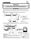
1.Since the video signal is common throughout the system, video will be present from the KCW-D/A when
any GF-1MD monitor is on.
2. Any 24V DC, 1A power supply can be used to power the KCW-D/A.
KCW-D/A TERMINAL DEFINITIONS:
DA1 2-Wire input from
DA2 KC or GF monitor
DV+ Coax output: Center cond.
DV- Coax output: Braided shield
b Not functional in GF System
E Not functional in GF System
+ Positive 24V DC
- Negative
Output Signal:
75 ohm, 1V peak-to-peak.
Coax: Solid copper core with copper braid.
WIRING DIAGRAM: KCW-D/A for Composite Video Output when any GF monitor is active
GF-1MD/
GF-1MDK
DA1
DA2
b
E
DV+
DV-
+
-
KCW-D/A
+
-
24V DC
Center cond. to
DV+
Braid to DV-
B1
B2
R1
R2
Composite
video output
B1
B2
GF-VBC/GF-4Z
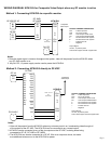
Method 1: Connecting KCW-D/A to a specific monitor
KCW-D/A TERMINAL DEFINITIONS:
DA1 2-Wire input from
DA2 KC or GF monitor
DV+ Coax output: Center cond.
DV- Coax output: Braided shield
b Not functional in GF System
E Not functional in GF System
+ Positive 24V DC
- Negative
Output Signal:
75 ohm, 1V peak-to-peak.
Coax: Solid copper core with copper braid.
DV+
DV-
b
E
DA1
DA2
+
-
KCW-D/A
Center cond. to
DV+
Braid to DV-
Composite
video output
Method 2: Connecting KCW-D/A directly to GF-VBC
R1
R2
GF-BC
+
-
PS-2410LC
A1 B1
A2 B2
A1 B1
A2 B2
A1 B1
A2 B2
A1 B1
A2 B2
A1 B1
A2 B2
B1
B2
+
-
GF-VBC
Out 1In 1
Out 2
In 2
Out 3In 3
Out 4
In 4
Out 5
In 5
Out 6
Notes:
1. Video will be present from the KCW-D/A when any entrance panel is on, broadcasting video through all
of the outputs of the GF-VBC. The KCW-D/A can be connected to any unused output.
2. KCW-D/A can be connected to any of the six outputs on the GF-VBC, including those being
connected to GF-4Z, GF-1MD or GF-1MDK.
3. The KCW-D/A can also be connected to a GF-4Z. Wire to an output as above, but make
sure additional wires are run to the KCW-D/A for power.
Pg. 2
A1
A2
GF-VA