


23-EN
Installation
Accessory List
• Head unit.............................................................................1
• Power cable.........................................................................1
• Mounting sleeve ..................................................................1
• Carrying case......................................................................1
• Bracket key..........................................................................2
• Screw (M5 × 8)....................................................................4
• Owner’s Manual.............................................................1 set
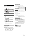
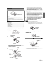
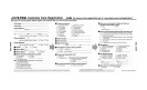
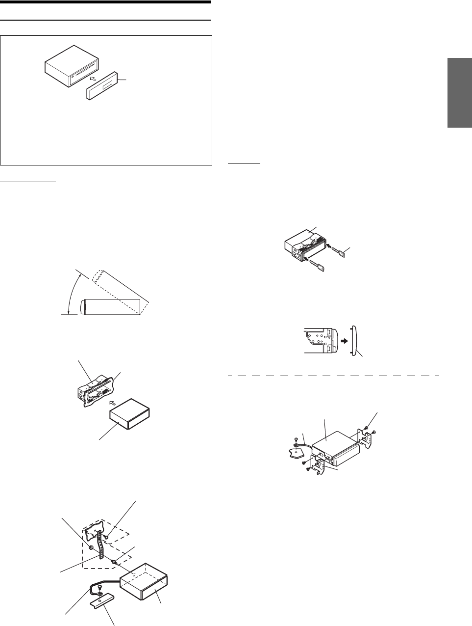
• The main unit must be mounted within 35 degrees of the horizontal
plane, back to front.
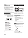
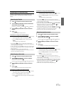
Removal
1. Remove the detachable front panel.
2. Insert the bracket keys into the unit, along the guides
on either side. The unit can now be removed from the
mounting sleeve.
3. Pull the unit out, keeping it unlocked as you do so.
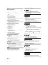
<JAPANESE CAR>
• Secure the ground lead of the unit to a clean metal spot using a screw
(*
3
) already attached to the vehicle’s chassis.
Caution
When you install this unit in your car, do not remove the
detachable front panel.
If the detachable front panel is removed during installation, you
might press too hard and warp the metal plate that holds it in
place.
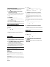
1
Remove the Detachable Front Panel (refer to page 6).
Slide mounting sleeve from main unit (see
“Removal” on page 23).
2
Detachable Front
Panel
Less than 35°
Mounting Sleeve
(Included)
Dashboard
This Unit
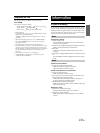
Metal
Mounting
Strap
Chassis
Hex Nut (M5)
Bolt Stud
Ground Lead
Screw
This Unit
*
2
*
1
Reinforce the head unit with the metal mounting
strap (not supplied). Secure the ground lead of the
unit to a clean metal spot using a screw (
*
1
) already
attached to the vehicle’s chassis.
• For the screw marked “*
2
”, use an appropriate screw for the chosen
mounting location.
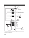
Connect each input lead coming from an amplifier or
equalizer to the corresponding output lead coming
from the left rear of the CDE-9852. Connect all other
leads of the CDE-9852 according to details
described in the CONNECTlONS section.
3
Slide the CDE-9852 into the dashboard until it clicks.
This ensures that the unit is properly locked and will
not accidentally come out from the dashboard.
Install the detachable front panel.
Bracket Keys
(Included)
This Unit
Face plate
this unit
Screws (M5 × 8)
(Included)
Mounting Bracket
Ground Lead
*
3