


Bulletin 095022-000 • Revision K • September 2003 • Page 2 of 2
DB404 Broad Band Antennas Andrew Corporation
DB404 SERIES INSTALLATION INSTRUCTIONS
1. Remove the antenna from the shipping box and ensure
that all parts are on hand and that there is no physical
damage.
2. Inspect the antenna feed assembly output connector to
determine that it mates with the end of your station trans-
mission line. Do not remove any connector or cable from
the antenna feed assembly; these are all a part of your
antenna.
3. Verify that the frequency to which the antenna has been
tuned is the frequency on which your radio system is to
operate.
4. Attach the furnished DB365 mounting clamps to the
bottom of the antenna mast at the designated locations.
Mount the antenna on the tower with the bottom dipole
above the tower.
5. A check of the antenna VSWR as measured at the an-
tenna is recommended at this point. Note this measure-
ment carefully and record it for future reference.
6. After checking the VSWR at the antenna, connect the
station transmission line to the antenna. (Make the con-
nection snug but do not apply heavy force from pliers.)
To avoid moisture problems, carefully wrap Vapor-
Wrap™ (Part # 11317 or 11316) around the connection,
working the compound into all cracks and smoothing it
over the outer jackets of the transmission line. Failure
to tape and waterproof the cable connection will result
in improper operation of your antenna. Properly secure
the feeder cable and antenna transmission line to the
tower in the best position to avoid physical damage.
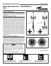
Side Mounting
When the DB404 and DB404L antennas are mounted to the side of a tower,
the horizontal radiation pattern necessarily becomes distorted. The follow-
ing indicates the typical pattern shape for an antenna that is side mounted
on a tower with an 18" face using the DB5007 Side Mount Kit. The pattern
for 12" and 24" towers will be similar.
The DB5007 Side Mount Kit positions the antenna approximately 16"
from the tower and consists of a galvanized bracket and the necessary
hardware for attaching the bracket to round tower members up to 3"
OD, or angular members up to 2-1/2" on a side. Other size clamps can
be supplied on special order.
DB404L, elements broadside to tower
DB404L, elements pointed toward tower
DB404 (Omni) mounted on side of tower
Andrew Corporation
Base Station Antennas
8635 Stemmons Freeway
Dallas, TX U.S.A. 75247
Telephone: 1-800-676-5342
FAX (U.S.A.): 1-800-229-4706
Internet: www.andrew.com
Customer Service, 24 Hour: U.S.A. • Canada • Mexico: 1-800-255-1479
U.K.: 0800 250055
Other Europe: +44 1592 782612
Printed in U.S.A.
Copyright © 2003 by Andrew Corporation
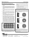
These curves illustrate the gain of the DB404 and DB404L across a
20 MHz bandwidth. Maximum gain of 3.8 dBd (DB404) and 5.0 dBd
(DB404L) occur at the mid-band frequency of each range. The gain of
the DB404L is shown at the pattern maximum in the horizontal plane.
(Continued from page 1)
7. After the antenna and transmission line installation is
complete, a careful visual check should be made to
ensure that:
• All mechanical connections have been securely made.
• The antenna is mounted on the proper leg of the tower
with sufficient physical clearance.
• All connections have been carefully wrapped with Va-
por-Wrap™ to prevent moisture problems.
Figure 3. Antenna Gain Curves
Figure 4. Typical Pattern Shape When Side Mounting
-10
3.0 db
4.0 db
5.0 db
6.0 db
-8 -6 -4 -2 fo +2 +4 +6 +8
ANTENNA GAIN vs FREQUENCY