


6
Installation Guide
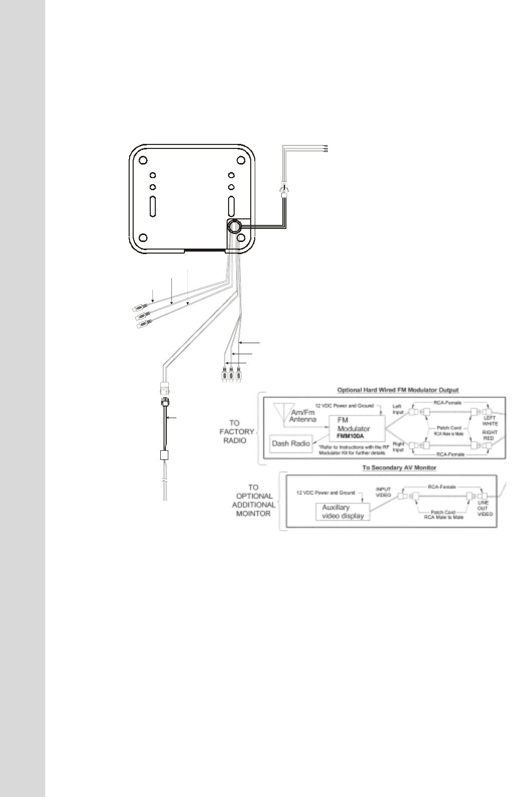
1) Make the connections to the vehicle for the 2 pin wiring harness.
2) Connect the 2 pin harness to the mating connector on the Video Monitor.
3) Connect power harness to vehicle's electrical system by tapping into an accessory hot line and a
good ground.
4) Verify all functions of the System before final mounting of the finished assembly.
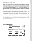
Note: A VCP or other A/V Component can be connected to the video monitor system using
the LINE IN RCA jacks.
A/V Source Definitions :
1 = Built-in DVD
2 = AV1 input ( VCD, Game or future DVD, etc )
3 = AUX input ( VCD, Game or future DVD, etc )
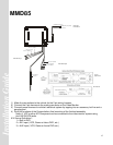
Line Out
Right and Left
MMD85
CHOKE
Auxillary
video display
12 VDC Power and Ground
INPUT
VIDEO
(Yellow)
Line Out-R (Red)
LINE
OUT
VIDEO
Patch Cord
RCA-Female
RCA Male to Male
Line Out-L (White)
Line Out-V (Yellow)
TO
OPTIONAL
ADDITIONAL
MONITOR
To Secondary AV Monitor
Power Harness
Item # 3
Line In-R (Red)
Line In-L (White)
Line In-V (Yellow)
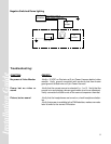
Red/Black (Lamp On)
Violet/Brown (Lamp Auto)
Black/Red (Lamp Common)
Line Video Out
Audio Video Output
Audio Video Input
Dome Light
Power Source