


1) Make the connections to the vehicle for the 2 pin wiring harness.
2) Insert the Circular Mini-Din Connector of the source component harness through the wire tie loop on
the main PCB and into the Mini-Din Connector on the main PCB.
3) Pull the wire tie loop tight and cut off the excess.
4) Connect the wired RF Modulator and / or the remote headphone jacks to the video monitor if those
options are being included.
5) Connect power harness to vehicle’s electrical system by tapping into an accessory hot line and a
good ground.
6) Verify all functions of the System before final mounting of the finished assembly.
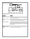
Note: A second VCP or other A/V Component can be connected to the video monitor system using a
second source component harness (purchased separately, part number: 8010730). This second har-
ness would plug into the second Mini-Din connector on the main PCB as in steps 2 and 3 above.
A/V Source Definitions:
1=
VCP (Right Mini-Din on main PCB)
2=
2
nd
VCP (or game or DVD, etc.…. left Mini-Din)
3= AUX-INPUT (RCA jacks on the face of the monitor).
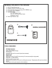
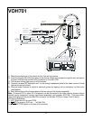
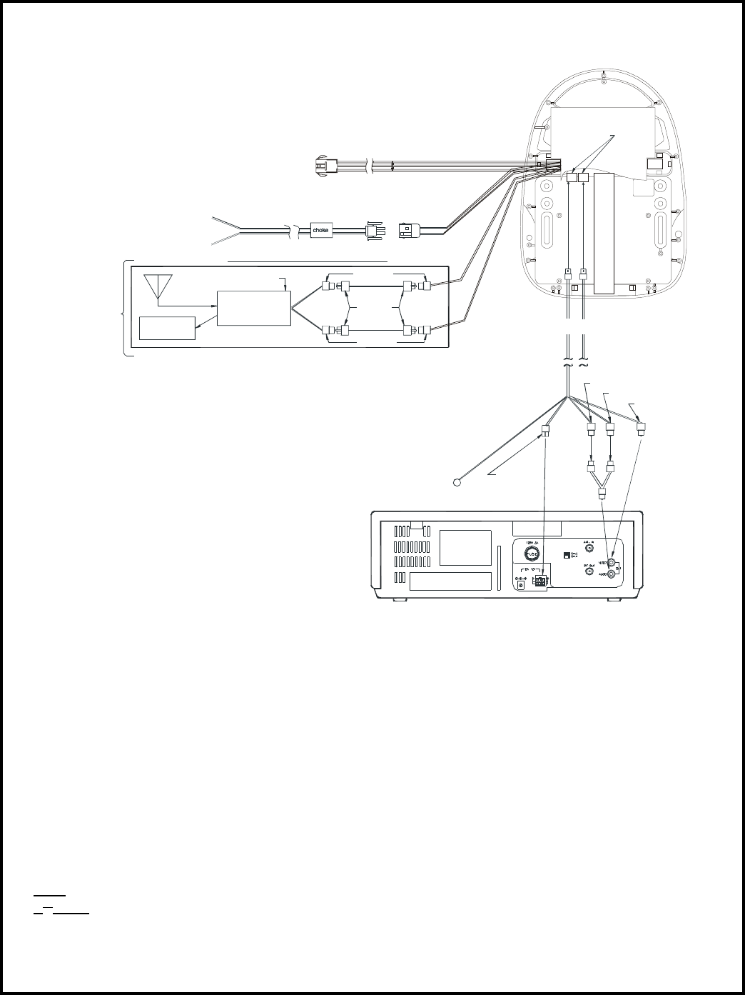
VOH701
Mini-Din Connectors
1 2
Antenna
Dash Radio
Red RCA (Audio Right)
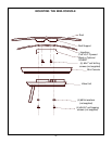
IR LED:
Clean the IR Receiver Window on the front of the VCP.
Remove Adhesive Backing and Apply IR LED to IR
Window on the Face of the VCP.
Yellow RCA (Video)
White RCA (Audio Left)
LEFT
WHITE
RIGHT
RED
Red: +12 VDC
(Accessory Cir.)
Power Harness
Item # 3
*Refer to Instructions with the RF
Modulator Kit for further details.
FM
Modulator
Optional Hard Wired FM Modulator Output
12 VDC Power and Ground
Black: Ground
Right
Input
Left
Input
Note: cables
exiting the pod
should be routed
as shown.
"Y" Adapter
for use with
Non-Stereo
Installations
Item# 5
TO
FACTORY
RADIO
1070610
Am/Fm
RCA-Female
RCA-Female
Patch Cord
RCA Male to Male
Power Connector
4 Pin
A
ccessory Harness
Item#2
Dome Light
Item #6
-6-