


8
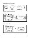
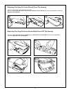
1) Make the connections to the vehicle for the 12 pin wiring harness.
2) Connect power harness to vehicle’s electrical system by tapping into an accessory hot line and a good
ground.
3) Connect the 12 pin harness to the mating connector on the Video Monitor.
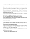
4) If an auxiliary video input is used (VCP, DVD, etc) insert the Circular Mini-Din Connector of the source
component harness through the wire tie loop on the main PCB and into the Mini-Din Connector on the
main PCB.
5) Pull the wire tie loop tight and cut off the excess.
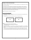
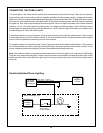
Note: A VCP or other A/V Component can be connected to the video monitor system using a source
component harness (purchased separately, part number: 8010730). This harness plugs into the Mini-Din
connector on the main PCB as in steps 4 and 5 above.(See Figure A on next page)
6) Verify all functions of the System before final mounting of the finished assembly.
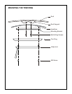
7) Mount and connect the Television antenna. (Optional)
A/V Source Definitions:
1. DVD – Built in DVD
2. AUX/Game
3. AV1 (DIN1)
4. AV2/ TV – Supplied 9 Pin to 3 RCA Jack Pigtail is used for AV2 input.
Optional TV Tuner (PODTVT2) is used TV input.
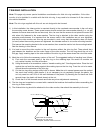
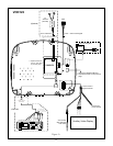
*NOTE: If the optional relay box P/N SIRSWB is installed, it recommended that the antenna for the wireless FM
Modulator be unplugged. See VOD122 Wiring Diagram for antenna location.
**NOTE: Extending the wireless antenna beyond its 12 inch length will cause the FM Modulator to exceed FCC
limits for wireless transmission. When installing the unit position the antenna for best reception.
***NOTE: If the optional TV Tuner (P/N PODTVT2) is installed the AV2 input becomes inactive.
VOD122