


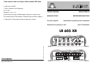


10
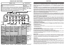
MULTICH.
Multichannel
In this
configuration
, the
amplifier
allows the
realisation of
a two-way
FRONT +
SUB system.
F
4
Lo pass cut-
off frequency
for WOOFER
channels, and
Hi-pass for
MID-TW
channels.
(
150Hz-850Hz
12dB/Oct.)
F
1
Lo pass cut-
off frequency
of SUB
channel
.
(
50Hz-150Hz
24dB/Oct.
)
F
2
Hi pass cut-
off
frequency
of WOOFER
channels.
(
50Hz-150Hz
12dB/Oct.)
F
3
Not
active.
OUT MID-TW
Hi-pass
preamplified
output of MID-
TW filter for a
supplementary
amplifier.
Signal level:
0 dB.
F/R
Front/Rear
In this
configuration,
the amplifier
allows the
realisation of
a Hi Pass
FRONT + Hi
Pass REAR +
SUB system.
F
4
Not
active.
F
1
Lo pass cut-
off frequency
of SUB
channel.
(
50Hz-150Hz
24dB/Oct.)
IN REAR
Input used to
drive REAR
channels.
F
2
Hi pass cut-
off
frequency
of FRONT
channels.
(
50Hz-150Hz
12 dB/Oct.)
F
3
Hi pass cut-
off
frequency
of REAR
channels.
(
50Hz-150Hz
12dB/Oct.)
IN FRONT
General input
to drive SUB
and FRONT Hi
Pass channels.
IN FRONT
General input to
drive SUB,
WOOFER and
MID-TW
channels.
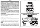
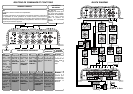
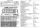
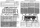
CONTROLS AND FUNCTIONS
ON
Lit when the amplifier is on.
SAFE
When lit, it indicates the intervention of protection circuits: in case of
overheating (temperature exceeding 80°C/176°F) or output anomalies (pre-
ence of continuous current, short circuit or dangerously low load impedan-
ce). When protection circuits intervene, the amplifier shuts down. Turn the
amplifier off. When the problem is corrected, turn the amplifier back on.
INDICATOR LIGHTS
V
1
- V
2
- V
3
Level adjustments for
SUB, FRONT/WOOFER
and REAR/MID-TW
channels (channels vary
according to the MODE
switch configuration).
LEVEL
CONTROLS
FREQUENCY CONTROLS
MODE
AUXILIARY
OUTPUT/INPUT
GENERAL
INPUT
1
1
11
FRONT
Left and Right power outputs for
FRONT channels. They are Hi
Pass filtered, in a range of
frequencies between 50Hz and
150Hz (12dB/Oct.), adjustable
through F
2
. The available signal is
STEREO. (Bridge configuration is
not possible).
REAR
Left and Right power
outputs for REAR chan-
nels. They are Hi Pass
filtered, in a range of fre-
quencies between 50Hz
and 150Hz (12dB/Oct.),
adjustable through F
3
.
The available signal is
STEREO. (Bridge confi-
guration is not possible).
F/R
Front/Rear
In this
configuration,
the amplifier
allows the
realisation of a
Hi
Pass FRONT
+ Hi Pass REAR
+ SUB system.
SUB
Power output for
SUB channels. It is
Lo Pass filtered, in a
range of frequencies
between 50Hz and
150Hz (24dB/Oct.),
adjustable through
F
1
. The available
signal is MONO.
(Mix L + R).
MULTICH.
Multichannel
In this
configuration,
the amplifier
allow
s the
realisation of a
two-way FRONT
+ SUB system.
SUB
Power output for
SUB channels. It is
Lo Pass filtered, in a
range of frequencies
between 50Hz and
150Hz (24dB/Oct.),
adjustable through
F
1
. The available
signal is MONO.
(Mix L + R).
WOOFER
Left and Right power outputs for
WOOFER channels. They are Hi
Pass filtered, in a range of fre-
quencies between 50Hz and
150Hz (12dB/Oct.), adjustable
through F
2
,and Lo Pass filtered, in
a range of frequencies between
150Hz and 850Hz (12dB/Oct.),
adjustable through F
4
. The availa-
ble signal is STEREO. (Bridge
configuration is not possible).
MID-TW
Left and Right power out-
puts for MID-TW chan-
nels. They are Hi Pass fil-
tered, in a range of fre-
quencies between 150Hz
and 850Hz (12dB/Oct.),
adjustable through F
4
.
The available signal is
STEREO. (Bridge confi-
guration is not possible).
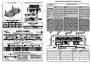
POWER
Input clamps for the
amplifier power supply.
Connect the battery
positive and negative
according to indicated
polarities.
Applied voltage must be
between 11 and 15 VDC.
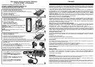
CONFIGURATION OF CONNECTING CLAMPS
OUTPUT CLAMPS
IN
Turn on control for the
amplifier coming from radio-
cassette player (or from any
sources provided with remote
control for amplifiers).
Applied voltage must be
between 7 and 15 VDC.
REMOTE
POWER SUPPLY
CLAMPS
VCR01
Connection
clamps for
the remote
volume
control,
VCR01
(optional).
SUB VOL.
CONTROL
OUT
Output leading to other
amplifiers of the sound
system. It has to be
connected to the REMOTE
IN of the following amplifier
to allow the simultaneous
turning on of the whole
system. Available voltage
equal to REMOTE IN.
MODE
1