


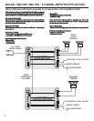


GENERAL INSTALLATION PROCEDURE
1
System Design
Installation
The success of any car stereo system relies on several factors, such as the system design, execution of the installation, and system setup. Please
remember that any system is only as good as its weakest link.
Please remember that higher power systems are not necessarily useful purely for high sound pressure levels, but also to establish a headroom capability, to
reproduce musical peaks cleanly without distortion. Lower power amplifiers will clip earlier than their more powerful cousins, and cause loudspeaker failure when
overdriven, due to the harmonics generated by a clipped signal, thus overheating voice coils.
Amplifiers should be mounted with the fins running horizontally for best convection cooling, to minimize overheating. Purchase the best quality RCA cables you can
afford, for reliability and less engine noise interference in the audio system.
General:
Run the wiring so that RCA cables are at least 18“ away from power and speaker cables. Keep RCA cables away from electrical devices in the vehicle that can cause
electrical noise, such as electric fuel pumps, emission control modules and other on-board electronic modules.
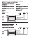
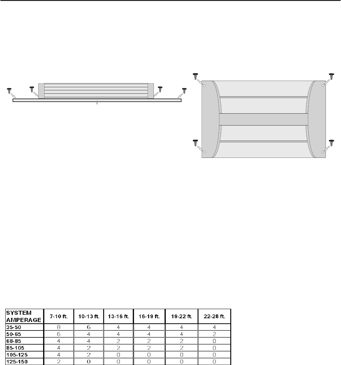
Power and ground connections(see the features matrix on page 8 for proper gauge cables per amplifier):
Use a sufficient gauge power cable and ground cable using the chart below as reference to what size wire you require. Street Machine series amplifiers require 4
gauge power wire. In a multi amplifier system, add the total value of the manufacture recommended fusing to get your total system amperage. Some applications
may require multiple runs of power wire to meet the system requirements. In multi amplifier systems it is advisable to mount a large enough fuse right at the battery,
and run one or multiple +12 volt power cables to a fused distribution block near the amplifiers. It is then a simple matter to connect the +12 volt terminal of each
amplifier to the distribution block. During this process, please ensure that the main power fuse is removed to avoid shorting the electrical system. The main fuse must
be within 12” of the vehicles battery.
Ground each amplifier with as short a ground lead as possible directly to the vehicle chassis using 4 gauge wire or equivalent to the size of the amplifiers’ power wire.
Use a ground distribution block, if you wish, but it is extremely important to keep the main ground lead from this distribution block to the chassis as short as possible ,
not more than 12“. The ground connection integrity to the chassis is very important, and the best way to achieve a good, solid electrical and mechanical contact is to
use a large round crimp lug, crimped and soldered to the ground cable. The next step is to scrape the paint off the vehicle chassis , slightly larger than the ground
lug, at the connection point. Drill a clearance hole in the chassis, the same size as the lug hole, and use a bolt, spring washer and nut to securely fasten the ground
lug. Use petroleum jelly to coat the bolt/lug connection, to prevent oxidization with time.
TIP: Use the same approach when installing head units, equalizers or any audio equipment for that matter - run short individual grounds from each piece directly to
the vehicle chassis, to minimize ground loops and system noise. All power, ground and speaker connections should be crimped and soldered for reliability. Make sure
that none of the cable insulation can chafe against exposed metal in the vehicle, causing short circuits to the chassis.
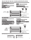
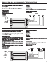
Safe connection sequence:
After all cables are run, connect speaker wires to the speakers and amplifiers, then run and plug in RCA cables. Next, connect all power, ground, and remote turn on
leads. Now connect all +12 volt cables to the amplifier/s and distribution blocks and fuse holders. Finally, connect the main +12 volt cable to the battery, with the main
fuse removed, and we are almost ready to power up the system.
Power up the system:
The following procedure may seem like overkill, but there is nothing more frustrating when turning on a system for the first time, and it does not work properly
immediately.
First, make sure the head unit is off, and turn all level controls to minimum (counterclockwise), including the head unit volume control. Set all equalizers to 0 dB (no
boost), and all crossover frequency controls at approximate frequencies, as recommended by the loudspeaker manufacturer. Set all input selector and crossover
switches as required for the application. Remove all amplifier fuses, and insert the main fuse at the battery. If the fuse does not blow, you can insert the fuse in one of
the amplifiers, and we are ready to turn on the system. Turn the head unit on, insert a CD, or select a radio station, and increase the head unit volume control. If the
system sounds fine, turn off the head unit, and install fuses in the remaining amplifiers, one by one, till the complete system is powered up and functioning properly.
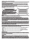
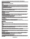
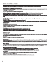
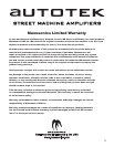
WOOD
It is highly recommended that the amplifier be mounted to a board of MDF or other solid
structure using the 4 mounting screws provided. Avoid mounting the
amplifier to metal as this can introduce noise and other unwanted issues. When mounting
the amplifier, ensure that it is mounted HORIZONTALLY, as shown in the diagram above, for
optimal heat dissipation. Mounting amplifiers to speaker enclosures is not recommended as
this can cause damage to the amplifier components. When choosing a location for
mounting the amplifier, ensure that you check for clearance from wires, gas tank, electrical
devices and brake lines etc.
NOTE: This Matrix is a general rule
of thumb. Please refer to the
manufacturers specific
requirements. Street Machine
specifications can be found on
page 8.