


13
DANSK
ENGLISH
DEUTSCH
FRANÇAIS
ITALIANO
NEDERLANDS
SVENSKA
ESPAÑOL
PORTUGUÊS
Supplied equipment
The signal converter is supplied with all
the parts listed below. Please check that
the range of parts supplied with your de-
vice is complete. If one of the listed parts
is missing, please contact your dealer
immediately.
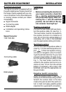
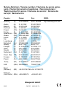
● Signal Converter
● Connecting cable
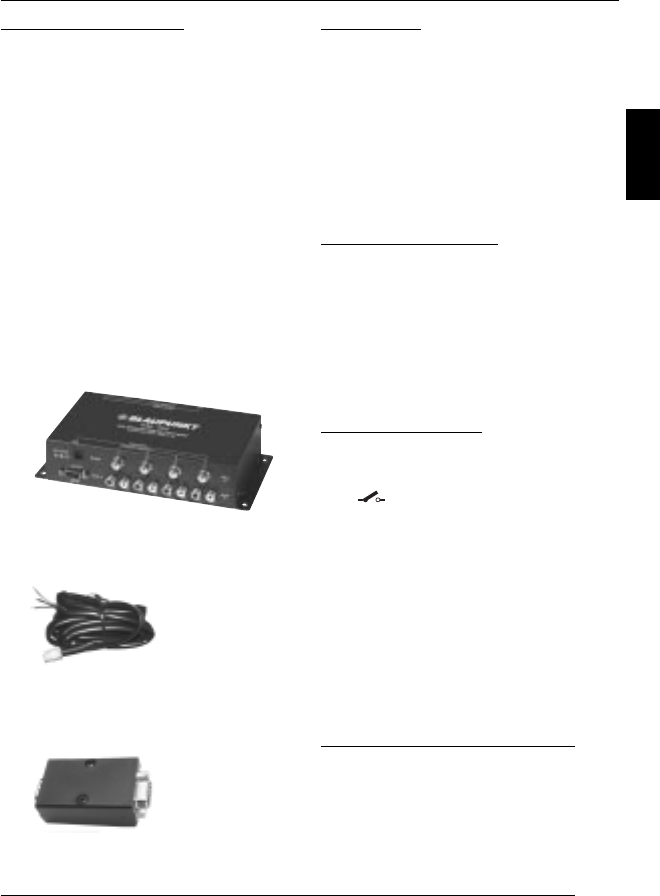
● RGB adapter
● Installation and operating instruc-
tions
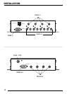
Signal Converter
7 607 003 550
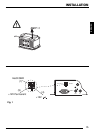
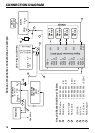
Installation
Note:
• Before connecting the monitors to
your signal converter, check that
the +/- and the switched positive
are connected properly. After con-
necting the +/- and the switched
positive, the red LED on the sig-
nal converter must light up!
Positive connection
Connect the fuse holder (5A fuse) to pro-
tect the positive cable (3) (see Fig. 1).
The fuse holder must be connected to
the positive terminal at a distance of
max. 30 cm from the vehicle battery (if
necessary, drill a hole in the bulkhead
use the appropriate cable grommets).
Switched positive
Connect the switched positive cable (4)
(see Fig. 1) to the switched positive out-
put (
) of the main system unit (e.g.
car radio or navigation unit). If connect-
ing to the vehicle’s terminal 15, you must
connect a fuse holder (1A fuse) to pro-
tect the switched positive cable (4) (see
Fig. 1). The fuse holder must be con-
nected to the positive terminal at a di-
stance of max. 30 cm from the vehicle
battery (if necessary, drill a hole in the
bulkhead and use the appropriate ca-
ble grommets).
Negative (earth) connection
Attach the negative cable (1) (see Fig. 1)
directly to the vehicle body using a screw.
Scratch the surface down to the bare
metal at the point at which the earth con-
tact is made and apply graphite grease
(important for a good earth connection).
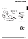
SUPPLIED EQUIPMENT INSTALLATION
Connecting cable
RGB adapter