


DANSK
15
ENGLISH
DEUTSCH
FRANÇAIS
ITALIANO
NEDERLANDS
SVENSKA
ESPAÑOL
PORTUGUÊS
INSTALLATION
Installation
Installation and safety notices
Before connecting your signal control-
ler, please read the following informa-
tion carefully.
The battery’s negative terminal must
be disconnected for the entire time it
takes to install and connect this device.
When doing so, observe the vehicle
manufacturer’s safety notices (airbags,
alarm systems, trip computers, immo-
bilizers).
Before drilling any holes, make sure that
no installed cables or vehicle compo-
nents can be damaged.
When installing the signal controller,
select a location in the vehicle that al-
lows you to attach it firmly into place
using screws. The installation location
should be such that the signal control-
ler does not get in the way of the driver
and cannot endanger the occupants in
the event of the vehicle suddenly com-
ing to a halt, for instance, during an
emergency stop.
The IR remote control should not be in-
stalled within the inflation range of air-
bags (driver, passenger side, side air-
bags) or in any position where it could
be struck by the vehicle occupants’
heads or knees.
With regard to the installation location
and the attachment using an adhesive
pad, check and ensure that the holding
strength of the installation surface is
sufficient and suitable for all situations
and safety requirements.
Note:
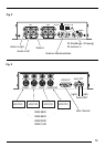
Before connecting the monitors to
your signal controller, check that the
+/- and switching positive connec-
tions are working properly.
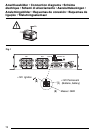
Positive connection
Connect the fuse holder (1A fuse) to
protect the positive cable (permanent
(1), see Fig. 1). The fuse holder should
be connected to the positive terminal at
a distance of max. 30 cm from the vehi-
cle battery (if necessary, drill a hole in
the bulkhead and use the appropriate
cable grommets).
Switching positive
Connect the switching positive cable (2)
(see Fig. 1) to the switching positive
output (ignition
) of the main de-
vice (e.g. car radio or navigation device).
If connecting to terminal 15 of the vehi-
cle, protect the switching positive cable
(2) by installing a fuse holder (1A fuse)
at a maximum distance of 20 cm from
the point of connection.
Fuse
If the fuse needs to be replaced, never
bypass/bridge the fuse and never re-
place it with fuse types that are designed
for higher currents.
Negative (ground) connection
Attach the negative cable (1) (earth/
GND, (3), see Fig. 1) directly to the ve-
hicle body using a screw. Scratch the
surface down to the bare metal at the
point at which the ground is made.
• If the installation requires holes to be
drilled or any other changes to be