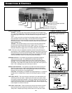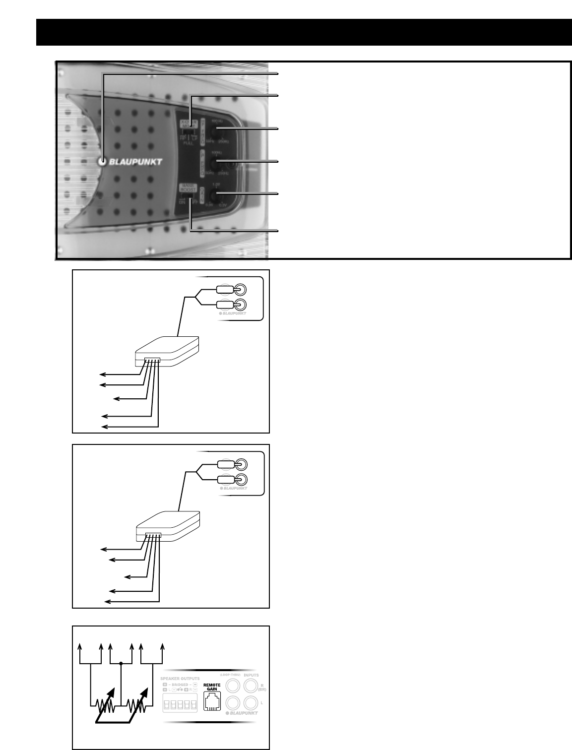
POWER ON LED - This light will turn on when the amplifier receives a
+12V turn on signal from the radio. If the amp is properly wired, but the
light does not turn on, there may be a short circuit condition that the amp
is protecting itself from.
BASS BOOST - This control provides additional bass in the 45Hz area to
give a stronger low end “feel” to the bass. Once switched on, this will
also allow the amp to be driven into distortion sooner so the user must
be aware.
GAIN CONTROL - The gain control allows for a range of 0.3-6Volts input.
This means that if the setting is a 0.3V, it only takes 0.3Volts to drive the
amp to full output. (Such a low setting allows for the amp to be easily
overdriven and more susceptible to noise so a mid-position is highly
recommended for most radios.)
LOW-PASS FREQUENCY - If the mode selector is in the “LP” position
the amplifier passes only low frequency sound. The upper limit for such
sound is set via this control. For bass, a value just below 100Hz is usually
best.
HIGH-PASS FREQUENCY - If the mode selector is in the “HP” position
the amplifier passes only mid and high frequency sound. The lower limit
for such sound is set via this control. A common setting is just above
100Hz.
CROSSOVER MODE - Depending upon the system design chosen, you
need to set the amplifier in the proper “mode” be it LP, Fullrange, or HP.
The low-pass and high-pass frequency settings are explained above. The
“full-range” setting simply allows for the amp to pass all audio frequencies
without any kind of crossover filter application. (This is common with
6x9” fullrange coaxial speakers for example.)
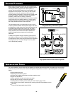
CONNECTIONS & CONTROLS
– 7 –
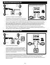
L (+)
L (–)
R (+)
R (–)
white
white/black
black
gray
gray/black
NOT
USED
"HLA1"
High Level Adaptor
(LOOP-THRU)
INPUTS
R
(BR)
L
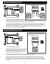
L (+)
R (+)
white
white/black
black
gray
gray/black
NOT USED
"HLA1"
High Level Adaptor
(LOOP-THRU)
INPUTS
R
(BR)
L
NOT USED
Radio chassis or
common speaker
ground
"Ganged" 20k/ch
Resistor pack
(L) (R)(GND)
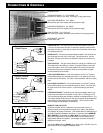
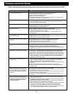
POWER ON LED
CROSSOVER MODE: LP - FULLRANGE - HP
(Crossover is either in Low-pass, Full-range, or High-pass mode)
HIGH-PASS FREQUENCY: “50 - 250Hz”
(Frequencies above this setting will be passed through)
LOW-PASS FREQUENCY: “50 -250Hz”
(Frequencies below this setting will be passed through)
GAIN CONTROL : “0.3 - 6.0 Vrms”
(this is the input voltage necessary at this position for full output power)
BASS BOOST: “ON/OFF”
(+10dB when ON)
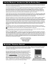
REMOTE GAIN CIRCUITRY
Should the installer wish to create their own remote gain control, or
attempt to daisy chain the gains of multiple amps, refer to the adjacent
circuit design for proper connection. This should ONLY be attempted by a
very highly qualified installation technician. If improperly done DAMAGE
WILL OCCUR to the amplifier and WILL NOT be covered by warranty!
(We put this information in this manual because of the interest of our
highly skilled Blaupunkt installers - the average consumer should NOT
attempt this on their own!)
You should ONLY loop the SIGNAL pin to other amps - DO NOT carry the
ground and +12V pin voltages to adjacent amps.
"Floating Ground"
Radio Outputs
"Common Ground"
Radio Outputs
REMOTE GAIN
CIRCUITRY


