


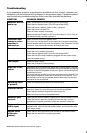

Troubleshooting
BASS1000 Amplified Subwoofer User’s Manual - page 10
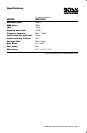
Specifications
BASS1000 Amplified Subwoofer User’s Manual - page 11
BASS1000 Amplified Subwoofer User’s Manual - page 5
BASS1000 Amplified Subwoofer User’s Manual - page 2
Introduction
BASS1000 Amplified Subwoofer User’s Manual - page 8
CONTENTS
BASS1000 Amplified Subwoofer User’s Manual - page 1
U S E R ’ S M A N U A L
BASS1000 Amplified Subwoofer User’s Manual - page 3
BASS1000 Amplified Subwoofer User’s Manual - page 4
BASS1000 Amplified Subwoofer User’s Manual - page 9
BASS1000 Amplified Subwoofer User’s Manual - page 6
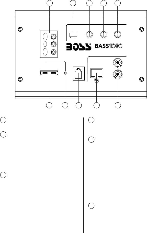
Controls and features
BASS1000 Amplified Subwoofer User’s Manual - page 7
Notes
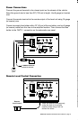
If you experience operation or performance problems with this product, compare your
installation with the electrical wiring diagram on the previous pages. If problems persist,
read the following troubleshooting tips which may help eliminate the problems.
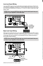
Low-level (RCA) input wiring is preferred for best audio performance. Most trunk
or hatchback installations will require a 15-20 foot RCA cable, while pickup trucks
and under-seat installations will require a 6-12 foot RCA cable. Always use a high-
quality cable.
Protection LED
comes on when
amplifier is
powered up.
Check for short circuits on speaker leads.
Turn down the volume control on the head unit to prevent overdriving.
Remote speaker leads, and reset the amplifier. If the Protection LED still
comes on, then the amplifier is faulty and needs servicing.
High hiss in the
sound.
Disconnect all RCA inputs to the power sub’s control panel. If the hiss
disappears, then plug in the component driving the amplifier and unplug
its inputs. If the hiss disappears at this point, go on until the faulty/noisy
component is found.
It is best to set the amplifier's input level control as low as possible. The
best subjective signal-to-noise ratio is achieved in this manner. Try to
set the head unit as high as possible (without distortion) and the amp
input level as low as possible.
Squealing noise
is present.
Check for improperly grounded RCA interconnects.
Distorted sound.
Check that the Input Level Control is set to match the signal level of the
head unit. Always try to set the Input Level as low as possible.
Check that all crossover frequencies are properly set.
Check for short circuits on the speaker leads.
Amplifier gets
very hot.
Check that the minimum speaker impedance for the amp model is correct.
Check that there is good air circulation around the amp. In some
applications, it may be necessary to add and external cooling fan.
Engine noise
(static type)
This is usually caused by poor quality RCA cables,which can pick up
radiated noise. Use only the best quality cables, and route them away
from power cables.
Engine noise
(alternator
whine)
Check that the RCA grounds are not shorted to the vehicle chassis.
Check that the head unit is properly grounded.
To Audio
Outputs of head
unit or signal
processor
6. Connect all line inputs and outputs (if
used) using high-quality cables. Connect
all speakers, following the diagrams in
this manual. Be sure to observe proper
polarity to avoid audio phase problems.
7. Insert fuse(s) into the battery fuse
holder(s).
8. Recheck all connections before
powering up the subwoofer.
9. Set all level controls to minimum
position, and set all crossover
controls/switches to the desired
frequency points.
10. Power up the head unit and the
subwoofer. Then set the volume control
on the head unit to about 3/4 volume,
and adjust the subwoofer's input level
controls to just below the level of
distortion.
11. Further fine tuning of the various
controls may be necessary to obtain best
results.
Connect the ground terminal to the closest point on the chassis of the vehicle.
Keep this ground wire to less than 39" (100 cm) in length. Use 8 gauge (or heavier)
wire.
Connect the remote terminal to the remote output of the head unit using 16 gauge
(or heavier) wire.
Connect an empty fuse holder within 18" (45 cm) of the car battery, and run 8 gauge
(or heavier) cable from this fuse to the amplifier location. Then connect the fuse
holder to the "BATT+" connection on the subwoofer rear panel.
Install the remote control securely
under the dash or in a similar
location where using it will not
distract the driver.
2 Introduction
2 What is included?
2 Features
3 General precautions
4 Protection circuitry
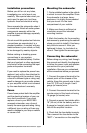
4 Installation precautions
4 Fuses
4 Mounting the subwoofer
4 Connecting the subwoofer
6 Front panel controls and features
8 Input wiring
9 Power connections
9 Remote level control connection
10 Troubleshooting
11 Specifications
Congratulations on your
purchase of a BASS1000
Amplified Subwoofer.
It has been designed, engineered
and manufactured to bring you
the highest level of performance
and quality, and will afford you
years of listening pleasure.
Thank you for making a
your choice for car audio
entertainment!
All specifications subject to change without notice.
page
BASS1000
12” Amplified Subwoofer
with Passive Radiator
MODEL
12” Amplified Subwoofer
SYMPTOM POSSIBLE REMEDY
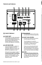
LOW PASS FILTER
This control permits you define the
frequency range you want the
subwoofer amplifier to receive. The
subwoofer will reproduce all sound
BELOW the frequency you set.
If the rest of your system is weak on
the mids, you may wish to set this
control relatively high. If the midrange
is well covered by the rest of your
system, you will probably want the
subwoofer to only receive lower
frequency signal.
3
PHASE SHIFT
Use this switch to help compensate
for time alignment problems in the
system. Such problems usually result
from having the subwoofer at a
different distance from the listener
than the other speakers in the system.
2
BASS BOOST
The bass boost feature will increase
the sound level in the bass frequencies.
4
INPUT GAIN CONTROL
After you have installed your system,
turn this control to minimum
Turn the head unit on (and the
subwoofer will turn on via the remote
connection). Turn the head unit
volume to about 2/3 full level.
Slowly turn up the subwoofer input
gain control until you hear a small
amount of distortion. Then reduce the
level until the distortion is completely
gone. Leave the control at this setting.
5
POWER TERMINALS
1
FUSE
The fuse in the upper socket is the
fuse which provides protection for the
circuitry. The fuse is rated at 25A. Do
not use a fuse with a different value
and NEVER replace the fuse with a
wire or coin.
6
WHITE GREY
GREY/BLACK
FUSE
POWER
GROUND
REMOTE
+12V
LOW PASS
FILTER
50Hz 150Hz
BASS
BOOST
0 +12dB
INPUT
GAIN
MIN MAX
INPUTS
LINE
LEVEL
L
R
HIGH LEVEL
REMOTE
LEVEL
CONTROL
PHASE
SHIFT
POWER STATUS
GREEN = ON
RED = PROTECTION
0 180º
AMPLIFIED SUBWOOFER
CONNECTIONS
1 2 3 4 5
6 7 8 9 10
Remote
Level Control