


AUDIO SYSTEMS
6
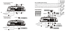
Electrical Wiring
Mounting the Amplifier
Remote Subwoofer Level Control
Wire the amplifier directly to the car battery. Make sure there is circuit protection (such as a fuse)
on the positive power lead, within 18 inches of the battery.
When making electrical connections to the amplifier, please observe the following:
Use at least 8 gauge or heavier wire for power and ground connections.
For the ground connection, use the shortest possible wire to a good chassis ground point.
Wire the Remote connection to the remote turn-on lead of your equalizer or head unit. In some cases
cases this may be the power antenna lead of the head unit.
Fuses
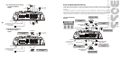
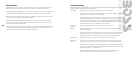
High Level Inputs
Four Channel Amplifiers:
GT 1180, GT 1380, GT 1480
CHANNEL 1 (+)
CHANNEL 1 (-)
CHASSIS GROUND
CHANNEL 2 (-)
CHANNEL 2 (+)
CHANNEL 4 (+)
CHANNEL 4 (-)
CHASSIS GROUND
CHANNEL 3 (-)
CHANNEL 3 (+)
From
HEAD UNIT
SPEAKER
OUTPUTS
WARNING: If you use the HIGH LEVEL (speaker) inputs, do not use the LOW LEVEL inputs at the same time.
The GT 4-Channel amplifiers utilize a separate connector
for Channels 1/2 and Channels 3/4.
Fuses protect both the amplifier and the electrical system of your vehicle from faulty conditions. If
you must replace the fuse in your GT amplifier, use a fuse of exactly the same type and rating.
A different type or rating may result in damage or cause a fire.
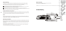
All BOSS GT series power amplifiers are equipped with a dashboard mount remote subwoofer
level control. Run the supplied dashboard remote control from the front panel of your amplifier. By
turning the level knob clockwise, you will increase the output of low frequencies.
All BOSS GT series power amplifiers are equipped with easy top access screw terminals. These
terminals are n in order to ensure excellent electrical contact and resist corrosion.ickel-plated
Mark the location for the mounting screw holes by positioning the amplifier where you wish to
install it and use a scribe (or one of the mounting screws) inserted in each mounting hole to mark
the mounting surface. If the mounting surface is carpeted, measure the hole centers and mark with
a felt tip pen.
Drill pilot holes in the mounting surface for the mounting screws and insert the mounting screws
into these holes. Tighten them securely.
Note: Before beginning your installation, be sure to take note of any wires, lines or other devices
in your vehicle which may be located behind any mounting surface.
HEAD UNIT
7