


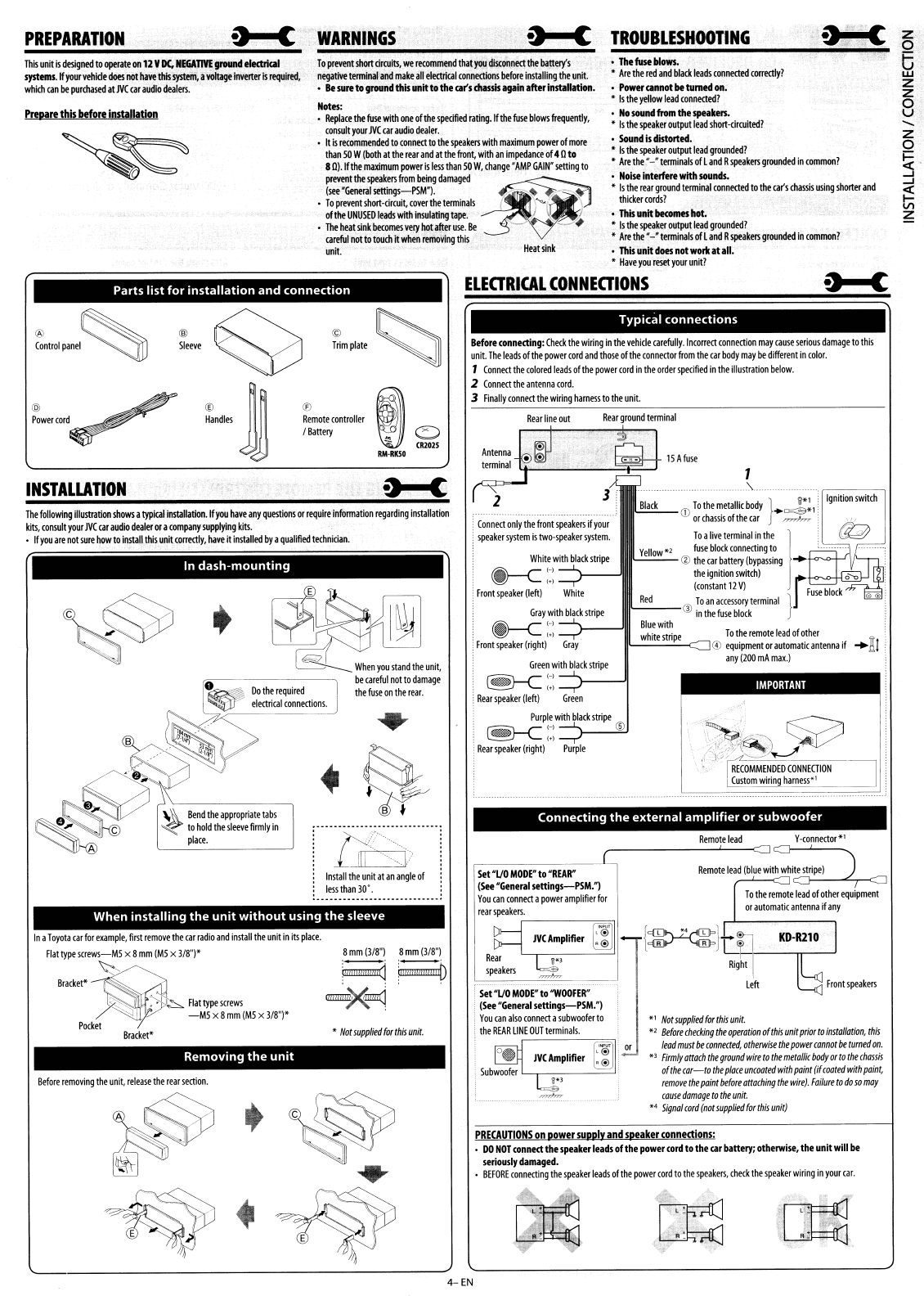
This
unit
is
designed
to
operate
on
12
V
DC,
N£CiAllVE
ground
eIectrIall
systems.
~
your
vehide
does
not
have
this
system,
a
voltage
inverter
is
required,
whkh
GIn
be
purchased
at
NC
Glr
audio
dealers.
z
o
6
w
z
z
o
u
.......
z
o
~
.....I
~
Z
•
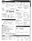
The
fuse
blows.
,
Are
the
red
and
black
leads
connected
correctly?
•
POWN
cannot
be
turned
on.
,
Is
the
yellow
lead
connected?
•
No
sound
fnMn
the
spukm.
,
Is
the
speaker
output
lead
short-{irrulted?
•
Sound
is
distorted.
,
is
the
speaker
output
lead
grounded?
,
Are
the"
-"terminals
of
land R
speakers
grounded
in
common?
•
Noise
intemre
with
sounds.
•
Is
the
rear
ground
terminal
connected
to
the
GI(s
chassis
using
shorter
and
thicker
cords?
•
This
unit
becomes
hot.
,
Is
the
speaker
output
lead
grounded?
•
Are
the
"-"terminals
oil
and
R
speakers
grounded
in
common?
•
This
unit
does
notworll
at
all.
•
Have
you
reset
your
unit?
TROUBLESHOOTING
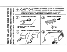
WARNINGS
To
prevent
short
clrruits,
we
recommend
that
you
disconnect
the
battery's
negative
terminal
and
make
all
elecl11G1I
connections
before
installing
the
unit.
•
Be
sure
to
ground
this
unit
to
the
ca(s
dlassls
again
attN
Installation.
Notes:
,
Replace
the
fuse
with
one
of
the
specified
rating.
If
the
fuse
blows
frequently,
coosult
your
JVC
Glr
audio
dealer.
• It
is
recommended
to
connect
to
the
speakers
with
maximum
power
of
more
than
50
W
(both
at
the
rear
and
at
the
front,
with
an
impedance
of
40
to
8
0).
~
the
maximum
power
is
less
than
50
W,
change'
AMP
GAIN"
setting
to
prevetltthe
speakers
from
being
damaged
~
(see
"General
settings-PSM'1.
-
~
-
•
TopreventShort-drCUIt,covertheterminaIS~""
\
of
the
UNUSED
leads
with
insulating
tape.
.
~
I
•
The
heat
~nk
becomes
very
hot
after
use.
Ie - -
~
Glreful
not
to
touch
It
when
removing
this
unit.
Heat
sink
PREPARATION
Preparethis
before
inSUlIation
Parts
list
for
installation
and
connection
ELEORICAL
CONNEOIONS
Y
-connector
*1
i~':""
t
~.
R
~
c_" " ,
IMPORTANT
1
.'.-
To
the
remote
lead
of
other
@
equipment
or
automatic
antenna
if .....
Xl
any
(200
rnA
max.)
.'.
~
~.
,:
..
u
..
;£-
)
<rc;»'(~
----
,.
Jj/
'--~~
RECOMMENDED
CONNECTION
Custom
wiring
harness·'
Remote
lead
1S
A
fuse
'~
~
Remote
lead
(blue
with
white
stripe)
"
Not
suppliedfor
this
unit.
"
Before
checking
the
operorion
oHhis
unit
prior
to
instollorion,
this
leod
must
be
connected,
otherwise
the
power
connot
be
rumed
on.
'3
Firmly
orrach
the
ground
wire
to
the
metallic
body
or
to
thechassis
of
the
car-to
the
place
uncoated
with
paint
(if
coated
with
paint,
remove
the
paint
before
arraching
the
wire).
Failure
to
do
so
may
cause
damage
to
the
unit.
,.
Signal
card
(not
supplied
for
this
unit)
Blue
with
white
stripe
Yellow"
}
'i/":
Ignition
switch
CD
Tothe
metallic
body
+=:5"!
orchassis
of
the
m
="="
; ,,
Toahvetermmalmthe
)
~
fuse
block
connectmg
to
'
®
thecar
battery
(bypassmg
....
+-O--.o--+--J.,
/l~_
thelgRitlon
SWitch)
0'0
(constant
12
V)
fFuse
block
IIL
__
Red
.:-...
__
®
To
an
accessorytermm,l
}
In
the
fuse
block
Rear
ground
terminal
Rear
line
out
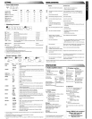
Connect
only
the
front
speakers
if
your
speaker
system
is
two-speaker
system.
Set
"Va
MODE"
to
"REAR"
(See
"General
setlings-P5M.")
You
can
connect
a
power
amplifier
for
rearspeakersr·
=~
White
with
black
stripe
~(-)
~(.)
Front
speaker
(left)
White
Gray
with
black
stripe
~(-)
~(-»
Front
speaker
(right)
Gray
Green
with
black
stripe
~l-)
~(.)
Rear
speaker
(left)
Green
Purple
with
black
stripe
~(-)
®
~(
..
)
Rear
speaker
(right)
Purple
Connecting
the
external
amplifier
or
subwoofer
Typical
connections
PRECAUTIONS
on powersupply andspeakerconnections:
•
DO
NOT
conne<lthespeaker
leads
ofthe
poweHord
to
the
car
battery; otherwise, the unit
will
be
seriously
damaged.
•
BEFORE
connecting
the
speaker
leads
of
the
power
cord
to
the
speakers,
check
the
speaker
wiring
in
your
car.
Set
"Va
MODE"
to
"WOOFER"
(See
"General
setlings-PSM.")
You
can
also
connect
a
subwoofer
to
•
the
REAR
LINE
OUTterminals.
Before
connecting:
Check
the
wiring
in
the
vehicle
carefully.
Incorrect
connection
may
cause
serious
damage
to
this
unit.
The
leads
of
the
power
cord
and
those
of
the
connector
from
the
car
body
may
be
different
in
color.
1
Connect
the
colored
leads
ofthe
powercord
in
the
orderspecified
in
the
illustration
below.
1
Connect
the
antenna
cord.
3
Finally
connect
the
wiring
harness
to
the
unit.
,
Not
supplied
for
this
unit.
8
mm
(1/8")
8
mm
(1/8")
illllllllllllllld
illlllllliiliill!lD
~X~'
,
•
.~
.--
~
....---_
..
--.....------_
..
C&,
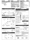
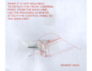
Install
the
unit
at
an
angle
of
less
than
10'.
When
installing
the
unit
without
using
the
sleeve
In
dash-mounting
, ,
._----_._-_.
__
.....
__
.------_.
€S?
~
When
you
stand
the
unit,
=------------,
be
careful
not
to
damage
the
fuse
on
the
rear.
Removing
the
unit
In
a
Toyota
car
for
example,
first
remove
the
car
radio
and
install
the
unit
in
its
place.
Flattypescre~w~~
x 8
mm(M5
x 1/8")'
Bracket*
~
:.
~
Flat
type
screws
-;:s
I
-MS
x8
mm
(M5
x1/8")'
Pocket
Bracket'
8efore
removing
the
unit,
release
the
rear
section.
~,."~~
®
~
©
Sleeve
Trim
plate
@
®
JJ
®
~
Power
cord
Handles
Remote
controller
Illattery
C)
(12025
RM-RIl50
INSTALLATION
...-c
The
following
iIIustratioo
shows
a
typiGlI
installation.
If
you
have
any
questions
or
require
information
regarding
installation
kits,
consult
your
JVC
car
audio
dealer
or
a
company
supplying
kits.
,
If
you
are
not
sure
how
to
install
this
unit
corre<tiy,
have
It
installed
by
a
qualified
technician.
4-EN