


TB0335B Page 5 of 10 10/18/03
AMPLIFIER ELECTRICAL CONNECTIONS
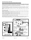
Disconnect vehicle battery before making the following electrical connections.
Electrical connections to the amplifier are made using the wiring harness supplied. If the amplifier needs service the
connector can be easily removed without unwiring the harness. The power supply for the amplifier must be capable of
delivering peak currents up to 50 amps for adequate short circuit protection and reliable operation. The preferred
source is directly at the vehicle battery. A fuse on the unit protects from overload.
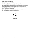
Wire Size and Termination - The diagram shows the minimum wire size used for each connection. If the wire is
longer than 10 ft. use the next larger wire size. Use only high quality crimp connectors for installation on the vehicle.
Negative Connection (Black) - Both leads must be used. Connect to negative battery connector or high current
buss.
Positive Connection (Red) - Both leads must be used. Connect to positive battery connector or high current buss. A
power relay may be used.
Speaker A Connection (Brown) - Both leads must be used. Connect 1 lead to each terminal or lead of the speaker.
Connect in same polarity (phasing) as Speaker B to assure loudest siren sound.
Speaker B Connection (Orange) - Both leads must be used. Connect 1 lead to each terminal or lead of the speaker.
Connect in same polarity (phasing) as Speaker A to assure loudest siren sound.
Control Connection (White) - Connect to white lead from control head. Route this lead away from radio transmitter
antenna lead to prevent RF interference being fed to the siren amplifier.
Optional Radio Input Connection (Blue) - Connect 1 lead to each terminal of the radio speaker or output connector.
The input is isolated and polarity is not important. May need to set RADIO VOLUME ADJUST on side of unit.
AMPLIFIER POWER
HARNESS CONNECTIONS
#18 AWG BRN
#14 AWG BLK
Use both leads
Extend with #12
#14 AWG RED
Use both leads
Extend with #12
-
BAT
+
CP3877
CABLE
+
-
SPKR
A
+
-
SPKR
B
#18 AWG BRN/BLK
#18 AWG ORG
#18 AWG ORG/BLK
Extend spkr leads with #16
For loudest siren sound
be sure speakers are wired
in same polarity.
RADIO
HRN/TT
MAN
WAIL
YELP
PHASR/W-Y
SIREN
PA
VOL
ON
POWER
GRN (AUX)
YEL (DASH LIGHTS)
BLK (-VDC)
RED (+VDC)
OFF/ON
BLK TO -VDC
RED TO +VDC
15AMP FUSE
A
UTOMOTIVE TYPE
RADIO VOLUME
A
DJUST
BLU TO TWO WAY
RADIO SPEAKER
WHT
CONTROL
FUSE A (SPKR A)
FUSE B (SPKR B)
CONTROL HEAD
AMPLIFIER
(CP3889
CABLE)
(CP3040 CABLE)
- ORG/BLK TO SPKR B -
+ ORG TO SPKR B +
- BRN/BLK TO SPKR A -
+ BRN TO SPKR A +
(CP3877 CABLE)