


TB0352A Page 4 of 8 09/27/05
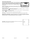
Cut to
Disable horn
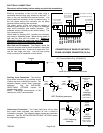
OPTION JUMPERS
FUSE
T-T
AUX I
PHSR
CUT P
AUX P
INSTALLER-SELECTABLE OPTIONS
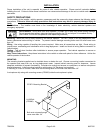
Carefully cutting programming resistor jumpers or traces on the printed circuit
board inside the case can select various options. The cover must be removed
to access the jumpers. The cover is held in place by a snap-fastener on the
back of the unit. Hold the unit with the front case flange on the edge of a hard
surface and press hard on the back of the unit. The chassis will slide out the
front of the cover.
Auxiliary Input Function - The auxiliary input normally activates the Horn
function. To activate the Man/Phsr function with the auxiliary input cut the
jumper resistor labeled "AUX I".
Auxiliary Input Polarity - The auxiliary input is normally activated by connecting to positive. To activate by
connecting to ground cut the two
jumper resistors labeled "AUX P".
Cutout Input Polarity - The cutout input is normally activated by connecting to positive. To activate by connecting to
ground cut the two
jumper resistors labeled "CUT P".
Two-Tone - Two-Tone can replace Phaser by cutting the jumper resistor labeled "T-T".
Phaser Disable - The Phaser function can be completely disabled by cutting the jumper resistor labeled "PHSR".
Horn Ring Cycler option (HRC) - This option allows selection of Wail, Yelp, Phaser and Standby by repeatedly
pressing horn ring or other switch connected to the auxiliary input. It is selected by cutting both the "AUX I" and
"PHSR" jumper resistors. This disables Phaser operation in the Wail or Yelp positions
Horn Disable - The Horn function can b e disabled by cutting the trace on the back of the
board at the location designated "cut to disable horn".