


Page 4 of 8 SA-500-20 28 Volt Installation and Operating Instructions
05/07/05 CP4930B
Wiring - Use wiring capable of handling the current required. Make sure all connections are tight.
Route wiring to prevent wear, overheating and interference with air bag deployment. Install and
check all wiring before connection to vehicle battery.
Testing - Test all siren functions after installation to assure proper operation. Test vehicle opera-
tion to assure no damage to vehicle.
Keep These Instructions - Keep these instructions in the vehicle or other safe place for future
reference. Advise the vehicle operator of the location.
UNPACKING
Inspect contents for shipping damage. If found alert carrier immediately
. Contents should in-
clude unit with attached microphone, mounting bracket, microphone bracket with 2 screws, 2
mounting bolts, removable terminal block plug, and these instructions. Contact supplier immedi-
ately if any components are missing.
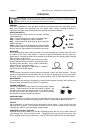
MOUNTING
The mounting bracket supplied can be installed above or below the unit. Choose a mounting
location convenient to the operator and away from any air bag deployment areas. Inspect behind
mounting area for clearance. Assure adequate ventilation to prevent overheating. Consider wire
routing and access to connections, as well as microphone bracket placement. Install mounting
bracket to vehicle using 1/4" hardware (not supplied).
If mounting in a rack or console, make sure that mounting bolts do not enter case more than 1/4".
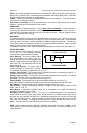
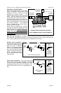
OPTION SWITCHES
Various options can be selected by turning on
or off any of 8 DIP switches internally
mounted on the right side of the PC board.
Cover Removal - The cover is held in place
by a snap-fastener on the back of the unit.
Hold the unit with the front case flange on the
edge of a hard surface and press hard on the
back of the unit. The chassis will slide out the
front of the cover.
Cutout Input Polarity - The cutout input is
normally activated by connecting to positive.
To activate by connecting to negative turn off "CUT_P".
Auxiliary Input Polarity - The auxiliary input is normally activated by connecting to positive. To
activate by connecting to negative turn off "AUX_P".
Auxiliary Input Function - The auxiliary input normally activates the Horn function. To activate
the Man/Phsr function with the auxiliary input turn on "AUX_I".
Two-Tone - Two-Tone can replace Phaser by turning on "T-T".
Phaser Disable - The Phaser function can be completely disabled by turning on "P_I".
Note: when Phaser is disabled the Man/Phsr pushbutton will toggle between Wail and Yelp.
Horn Disable - The Horn function can be completely disabled by turning on "H_I".
Yelp Override - Causes the Man/Phsr function to toggle to Yelp with selector switch in Wail
mode. Turn on "YLP_O".
Short Manual - The Manual function can be set to immediately cut off when the Man/Phsr
pushbutton is released. Turn on "SM".
Horn Ring Cycler 2 (HRC2) - Turn on “T-T” and “P_I” to enable this feature. Also connect the
auxiliary input to the horn ring or other switch. While the siren is in standby, tap the horn ring to
bring the unit out of standby into Wail tone. Repeatedly tapping the horn ring will cycle through
Wail, Yelp, and Phaser tones. Tapping the horn ring twice quickly will stop the siren tones and
return the unit to standby. Pressing and holding the horn ring will produce Horn tone until re-
leased. Then the siren will return to its previous siren tone or standby.
NOTE: Earlier models with S/N lower than 04190000 have a different version of HRC. In this
case the siren tones cycle through Standby, Wail, Yelp, and Phaser. The tone is stopped by cy-
cling to Standby.
OPTION SWITCHES
FUSE
SIDE VIEW
COVER REMOVED