


assembly to be quickly removed and replaced.
The rest of the assembly consists of the three-
polycotton/conex blend spiders. The two lower spi-
ders (mounted inverted to each other to cancel out
some of the non-linear behavior) are 8 1/2” in diam-
eter while the top spider is about 7” in diameter. All
three are progressive, which means they increase in
stiffness the further out they move in either direc-
tion. The dual four-layer voice coil is wound with
high-temperature copper wire on a black anodized
100mm (3.9”) diameter aluminum former. Voice coil
tinsel leads are connected to dual connecting
blocks on opposite sides of the frame. Each termi-
nal block has two sets of hex screw terminals that
accept up to 14-gauge wire, allowing the Stroker
Pro to be easily configured with the voice coils in
series or in parallel.
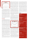
IN THE LAB
Part 1 of the objective measurement consists of
large signal analysis followed by the LEAP 5 analy-
sis. Using the Klippel analyzer (on loan from Klippel
GmbH), Pat Turnmire,
CA&E reviewer and CEO of
Redrock Acoustics, performed the large signal
analysis and provided the Bl (X) curve shown in
Figure 3. The black curve is the Bl curve and shows
the motor strength of the woofer as it moves in
both directions from center rest position. The lighter
curve is a type of displacement curve, and if both
curves were identical, the motor system’s motion in
and out of the frame would be perfectly symmetri-
cal. When a woofer is totally linear (linear would
mean that the woofer motion matches the input
signal exactly with no distortion), the Bl curve
should be centered on the 0mm point (where the
cone is positioned when there is no signal) and
symmetrically decrease with the same slopes in
both directions of voice coil travel. When a woofer
exhibits a forward or rearward offset it may indicate
the magnetic and mechanical systems are not
absolutely optimal. If the motor strength decreases
more rapidly in one direction (usually the outward
direction) than the other, the result is increased lev-
els of distortion at high operating levels. It is not
uncommon, however, for a woofer voice coil to be
deliberately offset a few millimeters in order to keep
the motor more linear in the 90-110dB SPL range,
which exactly describes the situation with the
Stroker Pro.
The Stroker Pro Bl (X) curve shows the woofer
voice coil is of
fset by a fairly trivial 2.5mm rearward
(inward) from its rest position. This Bl curve is a very
symmetrical, broad and flat plateau with nearly
equal slopes in either direction. The displacement
at operating SPL near Xmax is nearly 0mm, so this
is about as good as it gets. Bl can decrease to
approximately 70% of its small signal value and the
driver will still function in a satisfactory manner, only
with an elevated level of distortion (about 20%).
Since this is not really perceivable, it’s really not a
subjective problem. The 70% of maximum Bl dis-
placement limit for the Stroker Pro is 36.3mm,
4.8mm more than the physical Xmax of 32mm.
This subwoofer’s Kms(x) or Stiffness of
Suspension curve (see Fig. 4) likewise exhibits very
good symmetry in both directions of travel. The off-
set is a negligible 0.5mm rearward at the rest posi-
tion and transitions to about 2mm of also not-so-
significant forward offset as it reaches the physical
Xmax of the woofer. The compliance limit for the
suspension when it drops to 50% of its rest value is
greater than 38.1mm. Both “limit” numbers, Bl and
compliance, represent the level at which distortion
climbs to 20%, which is a realistic criteria for sub-
woofers given the ear’s lack of sensitivity to distor-
tion at low frequencies.
Next I generated the T/S (Thiele/Small) parame-
ters for the Stroker subwoofer. Following my usual
speaker geek test procedures, I used a LinearX
LMS (Loudspeaker Measurement System) analyzer
and VIBox for measuring dynamic impedance
(impedance at different voltages). Testing is accom-
plished by performing a series of voltage and cur
-
rent sweeps that are later converted to multiple
voltage impedance curves. With the driver clamped
to a rigid test stand, measurements were made at
1V, 3V, 6V, 10V, 15V, 20V, 30V and 40V. Rather than
use an added mass or test box method to find the
Vas (volume of air equal to the driver compliance) of
this driver, the measured weight of the cone body
(with 50% of the surround and 50% of the three
spiders removed) was used instead. This group of
multi-voltage impedance curves was copied into
the LEAP 5 software and the parameter model
derivation utility was used to produce the T/S para-
meters shown in the data chart. These numbers
were then used to generate the computer box sim-
ulation data provided in the Data Chart.
The Stroker Pro Thiele/Small parameters shown
in the Data Chart wer
e used to produce computer
box simulations using the Leap 5 Enclosure Shop
software. The software was configured to simulate
the woofer’
s low-frequency performance in the
same size boxes recommended in the Stroker Pro
manual, a 2.7ft
3
sealed box with no fill material and
a 3.0ft
3
ported box tuned to 36Hz with two 4” diam-
eter vents and also with no fill material. The LEAP 5
graph curves in Figure 3 show the SPL at 2.83 volts
(black curves) in half-space, 2.83 volts in an aver-
age 154ft
3
car compartment (blue curves), and at
the SPL at a power level required to get maximum
linear excursion (red curves, also half-space). The
sealed box curves are solid lines and the ported
enclosure curves are the dashed curves. The 2.83-
volt results produced an F3 of 43Hz for both box
types. Increasing the simulated input voltage for the
2.7ft
3
sealed box computer simulation to 150 volts
increased excursion to the Xmax +15% level and
pushed the SPL to a seriously devastating 126dB.
The 3.0ft
3
vented box computer simulation took
126 simulated volts to drive the Stroker Pro to just
beyond Xmax (Xmax + 15% or 36.8mm for the 15”
Stroker woofer) and resulted in an SPL of an
extremely loud 128dB! This monster definitely
Figure 3
Figure 4
B
rand
:
Cerwin-Vega
M
odel
:
Stroker Pro 15
MSRP: $1,699.00
W
arranty
:
1 year parts and labor
MECHANICAL SPECIFICATIONS
Weight
68.3 lbs.
Rear Mounting Clearance 9.75”
Woofer Magnet Dim.(dia.X ht. in mm) 260 x 20 x 2,
200 x 20
Voice Coil Diameter 100mm (3.93”)
Voice Coil Winding Layers 2x2 (two, two-layer coils)
MEASURED T/S PARAMETERS
Nominal Impedance
(ohms) 4
Revc (ohms) 3.65 (both 1.83-ohm voice
coils connected in series)
Sd (cone area in square meters)
0.087
Bl (motor strength in Tesla Meters) 22.2
Vas (in liters): 40.0
Cms (micrometers per Newton): 37.4
Mms (grams): 468.1
Fs (Hz): 38.7
Qms: 4.47
Qes: 0.83
Qts:
0.70
POWER AND EXCURSION DATA
Sensitivity
(2.83V/1M in dB): 86.1 series/92.1 parallel
Continuous P
ower Handling
(wa
tts RMS):
2,500
Peak Power Handling (watts): 5,000
Xmax ([coil length – gap height]/2 in mm): 38.6
COMPUTER SIMULA
TION D
ATA
Enclosure size for simulation (cubic feet)
Sealed: 2.7 (0% fill)
Vented: 3.0 (0% fill) tuned to 36Kz
-3dB (F3) at 2.83V
Sealed:
(Qtc=0.93):
43.0Hz
Vented: (Qtc=0.93): 43.0Hz
Voltage to achieve Xmax + 15%
Sealed:
150V
Vented: 126V
SPL at Xmax + 15%: (36.8mm)
Sealed: 126dB
V
ented:
128dB
DATA CHART