


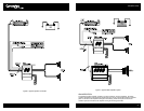


CONTROLS, INDICATORS, AND TERMINALS
INPUT PANEL
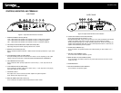
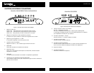
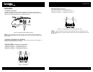
Figure 1: Input Panel Terminals and Controls
1. FILTER MODE SELECT SWITCH (MODE)
"HPF": Slide switch to this position if the amplifier is used as a mid/tweeter amplifier.
"OFF": Slide switch to this position if the amplifier is used as a full-range amplifier.
"LPF": Slide switch to this position if the amplifier is used as a subwoofer amplifier.
2. HIGH-PASS/LOW-PASS FREQUENCY SELECTOR KNOB (FREQ)
Adjust high/low-pass crossover frequency between 30 to 300Hz.
3. BASS BOOST CONTROL (BOOST)
Select a boost level between 0dB and +18dB to enhance the bass performance of your sound
system.
4. INPUT SENSITIVITY LEVEL CONTROL (SENS)
The input sensitivity level can be varied from 5.0 volts to 100 mV depending on the output
voltage of the source unit (refer to sub-section titled INPUT SENSITIVITY ADJUSTMENT).
5. HIGH IMPEDANCE INPUT (RCA)
To be connected to RCA pre-amp outputs from a source unit (i.e., radio, tape deck or CD
player).
6. LOW IMPEDANCE INPUT (SPKR LEVEL)
To be connected to speaker outputs from a source unit (i.e., radio, tape deck or CD player)
when RCA outputs are not available.
7. LINE LEVEL OUTPUT
This output can be used to connect to another amplifier for system expansion.
Note: This line level output is full range.
8. REMOTE SUBWOOFER GAIN INPUT (R S)
To be connected to the optional R S remote subwoofer volume control.
OUTPUT PANEL
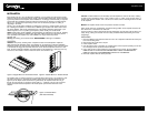
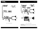
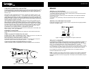
Figure 2: Output Panel Terminals and Indicators
9. POWER AND PROTECT INDICATOR (PWR/PRT)
Green light indicates that the amplifier is "ON".
Red light indicates either a high current, short circuit or DC offset is detected at the speaker
outputs. The amplifier will revert to normal operation once the problem is rectified.
The Red indicator also lights up at a high operating temperature. Under this condition, the
amplifier will automatically shut down. As soon as the temperature falls to a safe level, the
amplifier will automatically resume operation.
10. POWER INPUT TERMINAL (B+)
To be connected to the positive terminal of the vehicle’s battery or other constant +12 V
source.
11. GROUND INPUT TERMINAL (GND)
To be wired to the vehicle’s chassis for ground.
12. REMOTE TURN-ON INPUT TERMINAL (REM)
To be connected to the remote control wire or power antenna lead of the source unit for
remote ON/OFF.
13. FUSE RECEPTACLE
14. LEFT/RIGHT SPEAKER OUTPUT TERMINAL
For connection to the speaker system.
COUSTIC.COM
5