


(2)
Thank you for purchasing the MCA2250E 2.1 Channel Amplifier. It was designed and built to provide years of high quality
sound reproduction, and is ideal for use for music playback and computer audio systems. The amplifier includes features
like efficient Class “D” technology, independent amplifiers, selectable subwoofer crossover frequency, auto on/off circuitry,
and internal protection against shorted speaker loads, thermal faults, and overload conditions.
Features
:
• Independent high frequency and low frequency ampliers
• Efcient Class D technology
• Satellite level control
• Subwoofer level control
• Variable subwoofer crossover
• Switchable +3dB bass boost @ 63Hz
• RCA line level and 3.5mm stereo inputs
• Thermal, overload and fuse protection circuitry
• LED power status indicator
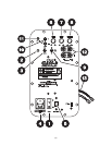
POWER SWITCHES AND INPUT
1.) Master ON/OFF Switch:
The amplier is manually turned ON or OFF via this master
switch. When the power switch is moved to the “ON” position,
the amplier will be in one of two modes depending on the
“On/Auto on” switch position.
2.) Indicator LED:
When the master switch is on and the indicator LED is red, the
amplier is in standby mode. When the On/Auto-On switch is
in the “On” position, the LED will stay green, and the amplier
is fully active. In the “Auto-On” position the LED will be green
and will turn to red after 10 minutes without a signal
Note: The master power switch will turn off the amplier re-
gardless of the “On/Auto on” switch setting.
3.) On/Auto-On Switch:
When the “On/Auto on” switch is in the “On” position the ampli-
er will operate normally. When in the “Auto-On” position the
amplier will operate normally when a signal (via RCA input) is
present and go in “stand by” mode when idle (no signal pres-
ent). It will take approximately 10 minutes for the unit to switch
from active to stand by mode. In standby mode the power draw
is less than 0.7W and heat generated is low therefore it is not a
problem to leave in the “Auto on” position indenitely.
Note: The Master “ON/OFF” power switch must be in the “ON” po-
sition to operate regardless of the “On/Auto on” switch setting.
4.) IEC Power Jack / Fuse Holder:
The unit comes with an IEC jack that permits removal of the
AC power cord. This allows the exibility of changing the power
cord for different countries. The IEC socket also houses the
main fuse holder. Plug the power cord supplied with the ampli-
er into the amplier and a grounded wall outlet or appropriate
surge protector. In most 230V applications a separate power
cord will be required and is not included.
Fuse: Replace with only 5mm x 20mm, fast blow 3.15A, 250V
type fuse for 115V operation and 2.5A for 230V operation.
5.) AC Voltage Switch:
The unit is set at the factory for 115V U.S. operation; simply
connect the included IEC power cord to your wall outlet.
For 230V operation, move the voltage selector switch to the
230V position. When operating at 230V the internal fuse
located in the IEC socket should also be changed. In most
230V applications a separate power cord will be required
and is not included.
Note: Be sure to change the fuse to a 2.5A rating before
switching to 230V operation.
LEVEL CONTROLS
6.) Satellite Level Control:
This adjusts the overall output level of the satellite amplier.
By adjusting both the satellite and subwoofer level controls,
the user will have the ability to blend the output levels of the
satellite and subwoofer speaker systems.
7.) Subwoofer Level Control:
Independently adjusts low frequency output level to the subwoof-
er only. Adjustment range is 0 ~ +5dB. Use this control to match
the subwoofer output level with the satellite output level.
8.) Subwoofer Frequency Control:
Independently adjusts low pass frequency to the subwoofer
only. Adjustment range of this active low pass crossover is 40
~ 240Hz with a 12dB / octave slope.
9.) Bass Boost (On/Off) Switch:
When in the “On” position the amplier subwoofer output is
increased 3dB centered at 63Hz. This will give the user added
bass output in the low frequency region.
Note: This switch should not be activated when the amplier is
being played at high volume levels, damage to the subwoofer
driver may result.
INPUT CONNECTIONS
10.) RCA Line Input:
RCA female connection accepts standard line level nominal
200mV p-p signal. This is suitable for connection to home equip-
ment as well as mixing console outputs in studio applications.
11.) 3.5mm Stereo Input:
The unit also features a 3.5mm stereo input jack for quick
connection to computers, MP3 players and other portable
electronic devices.
SPEAKER OUTPUTS
12.) Satellite:
The two pair (left “L” and right “R”) of binding post located on
the front panel, each color coded red “+” and black “-”, contain
an active 12dB/octave high pass lter @ 150Hz for satellite
speaker connection. Load on each output must have a nominal
impedance of 8 ohm or higher.
13.) Subwoofer:
There is one set of speaker outputs, red “+” and black “-” wires,
located on the rear (PC board side) of the amplier module.
More specically at the bottom of the larger PC board that is
perpendicular to the front panel. This amplied output contains
an active 12dB/octave variable low pass lter for subwoofer
speaker connection. Load on output must have a nominal
impedance of 4 ohm or higher.
CONTROLS AND CONNECTIONS