


4
© 1999 Directed Electronics, Inc
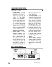
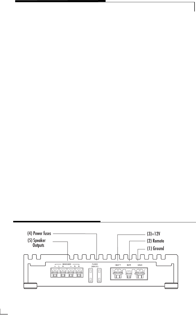
1. GROUND TERMINAL - connect this
terminal to the car chassis with a
short heavy gauge wire, DO NOT
CONNECT TO THE NEGATIVE
TERMINAL OF THE CAR BATTERY or
to factory chassis ground points
already occupied by factory wires! If
you are grounding multiple ampli-
fiers, you may use a high-current
distribution block with proper gauge
cables, or use individual grounds for
each amp attached to the vehicle at
separate but close ground points.
2. REMOTE TERMINAL - connect this
terminal to the amplifier remote
output from your head unit or signal
source, if it provides one. You may
also use the power antenna output
wire from decks that do not have
separate amp remote outputs. This
input requires a switched +12V
signal to activate the amplifier. Do
not connect this terminal to a
constant source of +12V.
3. +12V POWER TERMINAL - connect
this terminal to the positive terminal
of the car or separate audio system
battery. Refer to the installation
guidelines and specs page for proper
gauge of wire. YOU MUST PROTECT
THIS WIRE WITH A FUSE or circuit
breaker located close to the battery.
4. POWER FUSE - protects the ampli-
fier against electrical damage. DO
NOT REPLACE THE FUSE OR FUSES
WITH LARGER AMPERAGE FUSES !
If the fuse(s) blows, check your
system for wiring problems or see
your dealer.
5. SPEAKER OUTPUT TERMINALS
connect the speakers to these termi-
nals. Refer to the speaker wiring
diagrams (pg.6) for different wiring
options.
AMPLIFIER CONNECTIONS
Refer to Figure 1 for details.
FIGURE 1—AMPLIFIER CONNECTIONS