


AMPLIFIER SETTINGS
Signal Input and Output Configurations
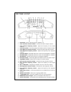
The input section of the amplifier consists of a phase switch that sets the output configura-
tion, gain controls, and RCA inputs. The input section makes it easy to adapt this amplifier
to most system configurations.
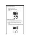
Four-Channel Amplifier Input Configuration
The 4CH / 2CH switch routes input from the front inputs to the rear section of the amplifi-
er. This allows the Orion 8004 channel amplifier to utilize a single set of RCA's to feed sig-
nal to the front and rear channels of the amplifier.
When the switch is to the right (2CH position), signal from the front inputs is routed to the
rear channels.When the switch is to the left (4CH position), front and rear inputs are inde-
pendent. This allows a source unit with an internal fader to fade between the front and rear
outputs.
Internal Crossover Configuration
The crossover section of Orion 8004 amplifiers is continuously variable and extremely flexi-
ble. There are eight different crossover configurations possible allowing high-pass, low-
pass, and band-pass operation. This circuit is designed to optimize the performance of sub-
woofers in all types of enclosures.
When using loudspeakers, minor deviations from the recommended frequency ranges can
provide superior results depending on your speaker locations and your vehicle acoustics.
Setting crossover frequencies higher than recommended will not cause damage and may
provide superior sonic results depending on your system's performance goals. Refer to your
loudspeaker owner's manual for assistance in choosing the proper crossover frequencies for
your system.
WARNING! DO NOT set crossover frequencies lower than the speakers recommended
operating range. This can cause driver failure that is not covered by manufac-
turer's warranty.
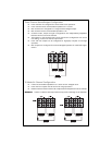
Low-Pass Crossover
When the switch is to the right (OFF position), the low-pass crossover is bypassed. When the
switch is to the left (ON position), the low-pass crossover is active. The low-pass crossover is
continuously variable from 20Hz to 3kHz.
High-Pass Crossover
When the switch is to the right (OFF position), the high-pass crossover is bypassed. When
the switch is to the left (ON position), the high-pass crossover is active. The high-pass
crossover is continuously variable from 20Hz to 3kHz.
High-Pass Woofers
The high-pass crossover is continuously variable from 20Hz to 3kHz. The high-pass crossover
is now optimized for use as a subsonic filter for subwoofers. Additionally, boost can be
added for improved bass output while still protecting the woofer from excessive excursion.
6
©2003 Directed Electronics, Inc.